USER MANUAL EN Edition: 3 from 05.02.2020 Supersedes the edition: 2 from 04.04.2019 Power supplies EN54C series v.1.0 Power supplies for fire alarm systems and smoke and heat control systems.
www.pulsar.pl EN54C RED POWER plus GENERAL SAFETY RULES Before installation, read the instruction manual to avoid errors that can damage the device and give you an electric shock. Before installation, cut off the voltage in the 230 V power-supply circuit. To switch power off, use an external switch, in which the distance between the contacts of all poles in the disconnection state is not less than 3mm.
www.pulsar.pl EN54C RED POWER plus TABLE OF CONTENTS 1. PSU FEATURES. ....................................................................................................................................4 2. FUNCTIONAL REQUIREMENTS OF THE PSU. ............................................................................5 3. TECHNICAL DESCRIPTION..............................................................................................................6 3.1. GENERAL DESCRIPTION. ..........................
www.pulsar.pl RED POWER plus EN54C 1. PSU features. Compliant with the requirements of the EN 54-4:1997+AC:1999+A1:2002+A2:2006 and EN 12101-10:2005+AC:2007 standards and pt. 12.2 of the Regulation of the Minister of Interior and Administration of the Republic of Poland of 20.06.
www.pulsar.pl RED POWER plus EN54C 2. Functional requirements of the PSU. The buffer power supplies for fire alarm systems has been designed in accordance with the following standards: - EN 54-4:2001+A1:2004+A2:2007 Fire detection and fire alarm systems. - EN 12101-10:2007+AC:2007 Smoke and heat control systems.
www.pulsar.pl RED POWER plus EN54C 3. Technical description. 3.1. General description. The buffer power supplies has been designed for an uninterrupted supply of fire alarm systems, smoke and heat control systems, fire protection equipment and fire automatics requiring stabilized voltage of 24 V DC (±15%).
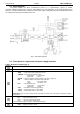
www.pulsar.pl RED POWER plus EN54C 3.2. Block diagram. The power supplies has been manufactured based on a high-efficiency system of AC/DC converter. Applied microprocessor circuit is responsible for the full diagnostics of the PSU parameters and batteries. The figure below shows a flowchart of the power supply, along with selected functional blocks which are essential for the proper functioning of the unit. Fig. 1. PSU block diagram. 3.3. Description of components and power supply terminals. Table 1.
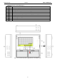
www.pulsar.pl EN54C APS – battery failure ALARM – collective failure AUX1 – AUX1 output voltage (at the AUX1 connector) AUX2 – AUX2 output voltage (at the AUX2 connector) PANEL LED – connector to the external LED indicators Battery temperature sensor Battery connectors; positive: +BAT = red, negative: - BAT = black Fig. 2. The view of the power supply module based on the EN54C-2A7.
www.pulsar.pl RED POWER plus EN54C Table 2. Elements of the PSU (Fig. 3). Component No. Description PSU (tab. 1, Fig. 2) Battery temperature sensor Battery connectors; positive: +BAT = red, negative: - BAT = black Place to install the EN54C-LB4 or EN54C-LB8 fuse module TAMPER; microswitch (contacts) of antisabotage protection (NC) Fitting battery Embossing for cable gland Embossings for concealed wires Lock Fig. 3. The view of the power supply based on the EN54C-2A7.
www.pulsar.pl EN54C RED POWER plus 4. Installation. 4.1. Requirements. The PSU is to be mounted by a qualified installer, holding relevant permits and licenses (applicable and required for a given country) for ~230 V in and low-voltage installations. As the power supply is designed for a continuous operation and is not equipped with a powerswitch, therefore, an appropriate overload protection in the power supply circuit should be provided.
www.pulsar.pl EN54C RED POWER plus 4.2. Installation procedure. CAUTION! Before installation, cut off the voltage in the 230 V power-supply circuit. To switch power off, use an external switch, in which the distance between the contacts of all poles in the disconnection state is not less than 3mm. It is required to install an installation switch with a nominal current of 6 A in the power supply circuits outside the power supply unit. 1.
www.pulsar.pl EN54C RED POWER plus 4.3. Procedure for checking the power supply at the place of installation. 1. Check the indication displayed on the front panel of the power supply unit: a) The 230 V LED should remain lit to indicate the presence of the mains supply voltage. b) The 230 V LED should remain lit to indicate the presence of the supply voltage. 2. Check the output voltage after 230 V power failure. a) Simulate the lack of 230 V mains voltage by disconnecting the main circuit breaker.
www.pulsar.pl EN54C RED POWER plus 5. Functions 5.1. Control Panel. The PSU is equipped with a LED panel allowing checking the current status of the power supply. Fig. 6. Control panel. Table 3. The description of the buttons and LEDs of the LCD panel. - green LED indicating 230 V voltage - green LED AUX indicating power at the AUX1 and AUX2 output of the PSU - yellow LED ALARM indicating collective failure 5.2. Technical outputs.
www.pulsar.pl EN54C RED POWER plus ALARM - technical output of collective failure indication. Output indicating collective failure. In the case of 230 V power failure, battery circuit failure, PSU failure, or EXTi input activation, the collective failure signal ALARM will be generated.
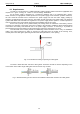
www.pulsar.pl EN54C Fig. 11. Example of a connection with the fuse module EN54C-LB8.
www.pulsar.pl EN54C RED POWER plus 5.4. Indication of the enclosure opening - TAMPER. The PSU is fitted with the microswitch tamper indicating enclosure opening. The tamper cable is not connected to the terminal in the factory settings. In order to activate tamper, remove the jumper from tamper terminal and plug in the tamper cable. Each opening the enclosure will generate a failure signal at the ALARM technical output. Fig. 12. TAMPER technical output. 5.5. PSU overload.
www.pulsar.pl EN54C RED POWER plus 5.7.2. Cooperation with electric actuators - EN54C-LS4 and EN54C-LS8 sequential modules. The sequential modules are designed for use with electric actuators without return spring (EN54C-LS4) and with electric actuators with return spring (EN54C-LS8) used for fire dampers and smoke vents. These devices are used in fire alarm systems and smoke and heat control systems.
www.pulsar.pl EN54C RED POWER plus 6. Reserve power supply circuit. The PSU is fitted with intelligent circuits: battery charging circuit with the function of the accelerated charging and battery control, which main task is to monitor the condition of the batteries and the connections in the circuit. If the controller detects a power failure in the battery circuit, appropriate indication and change of the ALARM technical output. 6.1. Battery detection.
www.pulsar.pl EN54C RED POWER plus Fig. 14. Mounting of the temperature sensor. The nominal battery operating temperature recommended by many manufacturers is 25°C. Working at elevated temperatures will significantly shorten the battery lifetime. The service life is reduced by half for each sustained temperature rise of 8°C above the nominal temperature. This means that the battery lifespan, when operated at 33°C, can be decreased by 50%! 6.8. Standby time.
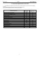
www.pulsar.pl RED POWER plus EN54C 7. Technical parameters. Electrical parameters (Table 4). Mechanical parameters (Table 5). Safety of use (Table 6). Operation parameters (Table 7). Recommended types and sections of installation cables (Table 8).
www.pulsar.
www.pulsar.pl RED POWER plus EN54C Table 5. Mechanical parameters. Battery space: 2x7 Ah 2x17 Ah W=330, H=305, D+D1=82+8 W=385, H=402, D+D1=88+8 Enclosure dimensions W 1=335, H1=308 [+/- 2mm] W 1=390, H1=406 [+/- 2mm] Mounting (WxH) 303x230 xΦ6 x4szt [mm] 358x325 xΦ6 x4szt [mm] Fitting battery 2x7 Ah/12 V (SLA) 2x17 Ah/12 V (SLA) (WxHxD) (max.
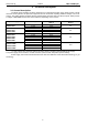
www.pulsar.pl RED POWER plus EN54C Table 7. Operation parameters. Environmental class EN 12101-10:2007 Operating temperature Storing temperature Relative humidity Sinusoidal vibrations during operation: 10 ÷ 50 Hz 50 ÷ 150 Hz Surges during operation Direct insolation Vibrations and surges during transport 1 -5oC÷40oC -25ºC...+60ºC 20%...90%, no condensation 0,1 G 0,5 G 0,5 J unacceptable According to the PN-83/T-42106 standard Table 8. Recommended types and sections of installation cables.
www.pulsar.pl EN54C RED POWER plus 8. Technical inspections and maintenance. Technical inspections and maintenance can be performed after disconnecting the power supply from the power network. The PSU does not require any specific maintenance, however, its interior should be cleaned with compressed air if it is used in dusty conditions. In case of fuse replacement, use only compatible replacement parts. Technical inspections should be carried out not less frequently than once per year.