
User Instructions

www.pulsar.pl HPSB11A12D GREEN POWER
3
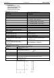
7. Buffer power supply unit 13,8V/2x12V/8x1A/40Ah.
- HPSB11A12D + 2xRN500(13,8V/12V) + 2xLB4 8x1A (AWZ575 or AWZ576) + 40Ah
8. Buffer power supply unit 13,8V/5x5V÷7,4V/5x2A/40Ah.
- HPSB11A12D + 5xDCDC20 (5V÷7,4V/5x2A) + 40Ah
9. Buffer power supply unit 13,8V/5x5V÷7,4V/10x1A/40Ah.
- HPSB11A12D + 5xDCDC20 (5V÷7,4V/5x2A) +5xLB2 10x1A (AWZ585 or AWZ586) + 40Ah
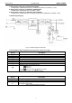
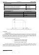
1.2 Block diagram (fig.1)
Fig.1. The block diagram of the PSU.
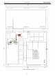
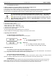
1.3 Description of PSU components and connectors ( tab.1, tab.2, fig.2).
Part no.
[Fig. 2]
Description
[1]
PSU module
[2]
connectors (see: tab.2)
[3]
green LED indicates AC power
[4]
potentiometer, output voltage adjustment
[5]
BAT+/GND: battery outputs + BAT=red, - GND=black
[6]
TAMPER, contact of sabotage protection (NC)
[7]
Additional connector for LED indication
[8]
Selection jumper for charging current:
Ibat =1 A
Ibat =4 A
Legend: jumper installed, jumper removed.
Factory settings: Ibat =1 A (jumper installed).
Tab.1. The components of the PSU.
Part no.
[Fig. 2]
Description
L, N
L-N power supply connector
PE
Protection connector (electric shock protection)
V+
V-
DC supply output
DC supply output (GND)
Tab.2. Output terminals of the PSU.