
User Instructions


www.pulsar.pl MSC1512
3
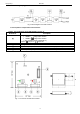
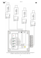
1.2. Block diagram (fig.1).
Fig.1. Block diagram of the PSU module.
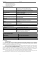
1.3 Description of components and connectors
Table 1. The components of the PSU module (see fig. 2).
Element no.
Description
[1]
J-Uout, pin- AUX output voltage adjustment
J-Uout = voltage AUX=12VDC*
J-Uout = voltage AUX=24VDC*
* - see: module’s supply voltage (tab. 3)
Caption: jumper on, jumper off
[2]
F1 fuse in the module’s power circuit
[3]
AUX, green LED: DC power indication
[4]
DC power output (+AUX= +U, -AUX=GND), see: J-Uout jumper configuration
[5]
AC, red LED: indication of AC (DC) supply voltage
[6]
AC or DC power input (transformer or PSU: II isolation class)
Fig. 2. The view of the MSC1512 module.