
User Instructions

2
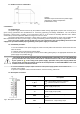
1.3. Output current vs temperature.
Graph 1.
Allowable output current from the power supply
depending on ambient temperature
(instantaneous load).
2. Installation.
2.1 Requirements.
The power supply shall be mounted by the qualified installer having appropriate (required and necessary for a
given country) permissions and qualifications for connecting (operating) low-voltage installations. The unit shall be
mounted in closed rooms, according to the environment class II, of the normal air humidity (RH=90% max. without
condensation) and the temperature within the range from -10°C to +40°C.
The power supply shall be mounted in a close casing (a cubicle, a terminal device) and in order to fulfill LVD and
EMC requirements the rules for power-supply, encasing and shielding shall be observed according to application.
Due to the power supply design, the PE wire has to be connected to the corresponding connector of the
supply unit. Operation without proper grounding of the power supply is not allowed!
2.2. Installation procedure.
1. Prior to installation of the power supply unit, make sure that power leads have been disconnected from the
230V AC mains.
2. Install the unit in the previously selected place.
3. Connect the 230V AC power leads. Connect the PE cable (yellow-green) to an appropriate terminal on the
power supply unit (marked with ).
The circuit of the shock protection shall be performed with a particular care, i.e. the yellow and
green protection wire of the power cable shall be connected from one side to the terminal marked
by the symbol of in the casing of the power-supply. Operation of the power-supply without the
properly made and fully operational circuit of the shock protection is UNACCEPTABLE! It can result
in failure of devices and electric shock.
4. Connect load/loads to proper output connectors of the power supply (positive end is marked as +V,
negative end as COM).
5. Upon the completion of tests and trial activation, close the housing, cabinet etc.
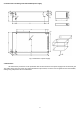
2.3. Description of terminal.
Elements/connectors [Fig.1]
Description
L, N,
L-N - input voltage connectors 230V AC,
– protective conductor connector
COM
Power supply output (0V)
+V
Power supply output (+48V)
LED1
LED signals the presence of voltage at the unit’s
output
Fig.1. Description of terminal.
ADJ
Potentiometer - output voltage adjust