
User Instructions

www.pulsar.pl PSACH01244
5
Operation safety (tab.4).
Protection class PN-EN 60950-1:2004
I (first)
Protection grade PN-EN 60529: 2002 (U)
IP65
Electrical strength of insulation:
- between input (network) circuit and output circuits of the PSU (I/P-O/P)
- between input circuit and PE protection circuit (I/P-FG)
- between output circuit and PE protection circuit (O/P-FG)
3000V AC min.
1500V AC min.
500V AC min.
Insulation resistance:
- between input circuit and output or protection circuit
100 MΩ, 500V/DC
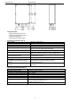
Operating specifications (tab.5).
Operating temperature
-25ºC...+40ºC
Storage temperature
-25ºC...+60ºC
Relative humidity
10%...90% without condensation
Vibrations during operation
unacceptable
Impulse waves during operation
unacceptable
Direct insolation
unacceptable
Vibrations and impulse waves during transport
PN-83/T-42106
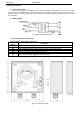
2. Installation.
2.1 Requirements
The AC/AC power supply is to be mounted by a qualified installer, holding relevant permits and licenses
(applicable and required for a given country) for 230V/AC interference and low-voltage installations. The unit
should be mounted in confined spaces, in accordance with the 2nd environmental class, with normal relative
humidity (RH=90% maximum, without condensation) and temperature from -25°C to +40°C (table 5). The PSU
shall work in a vertical or horizontal position.
Before mounting the PSU module, perform a load balance. During normal operation, total current drawn by
the receivers cannot exceed I=4A@24V AC.
As the PSU is designed for a continuous operation and is not equipped with a power-switch, therefore an
appropriate overload protection shall be guaranteed in the power supply circuit. Moreover, the user shall be
informed about the method of unplugging (usually through assigning an appropriate fuse in the fuse-box). The
electrical system shall follow valid standards and regulations.
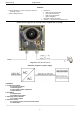
2.2 Installation procedure.
1). Before installation, make sure that the voltage in the 230V power-supply circuit is cut off.
2). Mount the PSU in a selected location and connect the wires (tighten cable glands).
3). Connect the power cables to the L-N terminals. Connect the ground wire to the terminal marked by the earth
symbol – “ ”. Use a three-core cable (with a yellow and green PE protection wire) to make the connection. Lead
the cables to the appropriate terminals of the connection board through the bushing.
The shock protection circuit shall be performed with a particular care, i.e. the yellow and green
wire coat of the power cable shall stick to one side of the terminal marked with the ' ' earth
symbol in the PSU enclosure. Operation of the power supply without a properly made and fully
operational shock protection circuit is UNACCEPTABLE! It can result in device damage or an
electric shock.
4). Connect the conductors of consumers to the terminals U1-0V and/or U2-0V of the terminal box on the power-
supply unit (the balance of the power-supply load shall be performed).
5). Restore the mains power ~230V AC.
6). Once the tests and control operation have been completed, close the PSU.