
Modbus Protocol

Strona 4 z 5
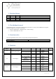
F04 - Output overload
3
1-bit
0 – inactive
1 – active
F04 - Output overload -
off
4
1-bit
0 – inactive
1 – active
F50 - Internal supply
fail
5
1-bit
0 – inactive
1 – active
F50 - Internal supply
fail
6
1-bit
0 – inactive
1 – active
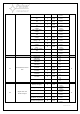
F07 - High battery
voltage
7
1-bit
0 – inactive
1 – active
F06 - High AUX
voltage
8
1-bit
0 – inactive
1 – active
F08 - Charge circuit
fail
9
1-bit
0 – inactive
1 – active
F10 - Low battery
voltage
10
1-bit
0 – inactive
1 – active
F11 - Low battery
voltage – off
11
1-bit
0 – inactive
1 – active
F09 - Low AUX
voltage
12
1-bit
0 – inactive
1 – active
F12 - External input
EXT
13
1-bit
0 – inactive
1 – active
F51 - Internal supply
fail
14
1-bit
0 – inactive
1 – active
F01 - AC power fail
15
1-bit
0 – inactive
1 – active
05
Led indication, Buzzer
state
Charge level
LED 30%
0
1-bit
0 – off
1 – on
R
Charge level
LED 60%
1
1-bit
0 – off
1 – on
Charge level
LED 90%
2
1-bit
0 – off
1 – on
Led EXT
3
1-bit
0 – off
1 – on
Led OVL
4
1-bit
0 – off
1 – on
Led PSU
5
1-bit
0 – off
1 – on
Led APS
6
1-bit
0 – off
1 – on
Buzzer
7
1-bit
0 – off
1 – on
06
Signals state and
technical output
Battery charging
0
1-bit
0 – inactive
1 – active
R
Battery test in progress
2
1-bit
0 – inactive
1 – active
Technical input EXT
3
1-bit
0 – inactive
1 – active
Technical output APS
8
1-bit
0 – inactive
1 – active
Technical output PSU
9
1-bit
0 – inactive
1 – active
Technical output EPS
10
1-bit
0 – inactive
1 – active