
User Instructions

www.pulsar.pl PSUPS10A12CR
7
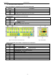
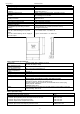
Table 7. Operating specifications
Environmental class
II
Operating temperature
-10ºC...+40ºC
Storage temperature
-20ºC...+60ºC
Relative humidity
20%...90%, without condensation
Vibrations during operation
unacceptable
Impulse waves during operation
unacceptable
Direct insolation
unacceptable
Vibrations and impulse waves during transport
Wg PN-83/T-42106
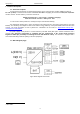
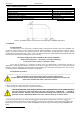
Chart 1. Acceptable output current from the PSU depending on ambient temperature.
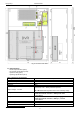
2. Installation.
2.1 Requirements.
The buffer PSU is to be mounted by a qualified installer, holding relevant permits and licenses (applicable and
required for a given country) for 230 V interference and low-voltage installations. The unit should be mounted in confined
spaces, in accordance with the 2nd environmental class, with normal relative humidity (RH=90% maximum, without
condensation) and temperature from -10°C to +40°C. The PSU shall work in a vertical position that guarantees sufficient
convectional air-flow through ventilating holes of the enclosure.
The power supply load balance should be done before installation:
Output current 8x0,75 A + 4 A recorder + 1 A battery charging*
Total current of the receivers + battery 11 A
*
max.
As the PSU is designed for a continuous operation and is not equipped with a power-switch, therefore an
appropriate overload protection shall be guaranteed in the power supply circuit. Moreover, the user shall be informed
about the method of unplugging (most frequently through separating and assigning an appropriate fuse in the fuse-box).
The electrical system shall follow valid standards and regulations.
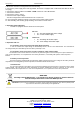
2.2 Installation procedure.
Before installation, cut off the voltage in the 230 V power-supply circuit.
To switch power off, use an external switch, in which the distance between the contacts of all
poles in the disconnection state is not less than 3mm.
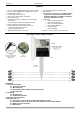
1. Mount the PSU in a selected location and connect the wires.
2. Connect the power cables (~230 V) to L-N terminals of the PSU.
The shock protection circuit shall be performed with a particular care, i.e. the yellow and green
wire coat of the power cable shall stick to one side of the terminal - marked with ‘‘ symbol on
the PSU enclosure. Operation of the PSU without the properly made and fully operational shock
protection circuit is UNACCEPTABLE! It can cause a device failure or an electric shock.
3. Connect the ground wire to the terminal marked with the symbol (power supply module connector). Connect the
ground wire to the clip marked by the earth symbol . Use a three-core cable (with a yellow and green protection
wire) to make the connection. Lead the cables to the appropriate clips through the insulating bushing of the connection
board.
*
See chart 1