
User Instructions

www.pulsar.pl PSUPS20A12CR
4
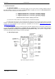
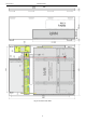
1.3. Description of PSU components.
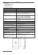
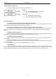
Table 1. Description of components and connectors module LB8
Component no.
[Fig. 2]
Description
F1÷F8 glass fuses
L1÷L8 LED voltage indication at the outputs
AUX1 ÷ AUX8 independently protected outputs
IN1-, IN2- power supply inputs of the fuse module
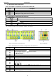
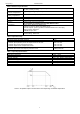
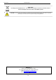
Table 2. Description of components and connectors
Component no.
[Fig. 3]
Description
F
AUX
glass fuses
protection connector
AUX – output
IN – power supply inputs, output filter
The enclosure contains 2 fuse modules for powering 16 cameras.
Fig.2. The view of the fuse module LB8.
Fig.3. Output filter.
Table 3. Description of the module’s components and connectors.
Component no.
[Fig. 4]
Description
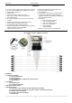
PSU module PSB-30012200
Connectors of the PSU:
L-N 230 V power connector, protection connector
V+, V- DC supply outputs
B+, B- battery output
green LED indicates DC power
P1 potentiometer, output voltage adjustment
Battery outputs: red: +, black: -
TAMPER, contact of tamper protection (NC)
Battery charging current selection:
Description: jumper on, jumper off
Fuse module LB8
DC/DC 50SE-SEP converter
Output filter
Cable for supplying recorder there is plug DC 2,1/5,5