
User Instructions

www.pulsar.pl RCB48V RACK POWER
7
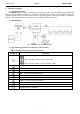
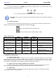
3.2. Technical output.
The controller is fitted with the ALARM technical output of collective failure. The collective failure can be
triggered by the events presented in Table 6.
Fig. 6. The electrical diagram of the ALARM output of collective failure.
CAUTION! In Fig. 6 the set of contacts shows a potential-free status of the relay which corresponds
to a failure.
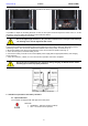
3.3. Acoustic indication.
The failure status is also signaled acoustically by means of a piezoelectric indicator (in accordance with
Table 6). Acoustic indication can be disabled with an ON/OFF switch .
Switch in the upper position, the indication is ON
Switch in the lower position, acoustic indication is OFF
Table 6. Table of errors
State, failure
Optical
indication
Acoustic
indication
Technical
output
Causes, comments
The start of the test
Absence
2 short beeps
INACTIVE
- Start of the battery test
High resistance of the
BAT circuit
Blinks
1 beep every 10
seconds
ACTIVE
- Batteries worn out
- Loose connectors
Undercharged battery
Blinks
1 beep every 10
seconds
ACTIVE
- Undercharged battery
No battery
Blinks
1 beep every 10
seconds
ACTIVE
- Blown F
BAT
fuse
- No battery
Low battery voltage (DC
operation)
Lit
2 short beeps
every 10 seconds
ACTIVE
- The batteries voltage has
dropped below 46V during battery
(assisted operation)
Low battery voltage -
disconnection (DC
operation)
Absence
2 beeps every 10
seconds (without
repeat)
ACTIVE
- The batteries voltage has
dropped below 42V during battery
(assisted operation)
4. Maintenance and operation.
4.1. Automatic battery test
The battery controller performs a battery test every 5 minutes, temporarily stopping the charge process,
while measuring voltage at the battery terminals and the resistance of the battery circuit. The test can also be
started manually by pressing the "TEST" button on the front panel, but not more often than once every 1 minute.
The activation or deactivation of the test will be confirmed acoustically (see Table 6).
4.2. Short circuit of the controller output/reverse connection.
The BAT controller output is additionally protected against short circuit by a fuse (box); in the case of
damage, it should be replaced with a fuse of the same type. The fuse is located inside the unit.
4.3. Maintenance.
The battery controller does not require any specific maintenance; however, it should be cleaned with
compressed air if used in dusty conditions.