
Specifications


EMC-CS-2009.1
© Copyright Ford Motor Company – All Rights Reserved Page 103 of 121
February 11, 2010
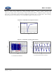
Figure D-5: CI 220 Pulse C Characteristics
-400
-300
-200
-100
0
100
200
300
0.0 0.5 1.0 1.5 2.0 2.5 3.0 3.5 4.0
usec
Volts
a) Pulse A2-1
-250
-200
-150
-100
-50
0
50
100
150
200
-150 -100 -50 0 50 100 150
usec
Volts
Contact Break
Contact Make
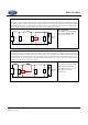
c) Pulse A2-2
-400
-300
-200
-100
0
100
200
300
0.0 0.5 1.0 1.5 2.0 2.5 3.0 3.5 4.0
usec
Volts
b) Pulse C-1
-250
-200
-150
-100
-50
0
50
100
150
200
-150 -100 -50 0 50 100 150
usec
Volts
Contact Make
d) Pulse C-2
Pulse E represents the voltage transient produced during switching of a higher current (> 5 ampere) inductive load that shares
the same circuit with the DUT. The test pulse is equivalent to Test Pulse 1 delineated in ISO 7637-2. Pulse E is similar to
Pulse A-1 except that it occurs when higher current loads (> 5 amperes) share the same circuit as the inductive load. The
pulse can also occur on circuits with high capacitive loads (> 2uf). Pulse E characteristics are illustrated in Figure D-6.
D.2 Test Pulse F1 and F2
Pulse F1 simulates the interruption of a current through an inductance switched in series with the DUT. The test pulse is
equivalent to Test Pulse 2a delineated in ISO 7637-2. Application of this test pulse is limited only for power supply circuits
and
only for components required to meet the ESA requirements of European directive 72/245/EEC.
Pulse F2
simulates the interruption in current to brush commutated motor, which is low-side switched. The test pulse is
equivalent to test pulse 2B delineated in ISO 7637-2. Application of this test pulse is limited only for power supply circuits
and
only for components required to meet the ESA requirements of European directive 72/245/EEC.