
Specifications


EMC-CS-2009.1
© Copyright Ford Motor Company – All Rights Reserved Page 109 of 121
February 11, 2010
Annex E (Normative): Transient Waveform Application
Applications of Test pulses A, C, E and G are largely dependent on how the DUT is connected to the power distribution
system. This annex provides basic information with respect to application for each transient test pulse. The figures
presented represent typical configurations including the ignition switch, remote switch (SW2), inductive load, the DUT and
external electronic loads "Z" connected at various points on the power distribution system. Proper application of transient
pulses requires analysis of how the actual component (DUT) will be used. In many cases the actual device configuration will
be some combination of the generic configurations presented.
Application of Pulse F1 nor F2 are limited to power supply circuits for compoents required to demonstrate compliance to the
ESA requirements delineated in 72/245/EEC.
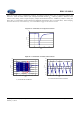
Configuration 1
DUT power circuit "A" shares the same circuit as the inductive load (e.g. window lift motor). The DUT and
inductive load are switched via SW2. Transient pulses A1, A2 and E will be present at "A" if IGN SW remains
closed and SW2 opens. Pulses C and G (load dump) will be present at "A" when IGN SW and SW2 are closed.
Pulse Application
+
_
SW2
L
W2
BATT
IGN SW
L
W1
L
W1
, L
W2
<< L
R
L
Inductive
Load
DUTDUT
A
Z
2
Z
2
Z
1
Z
1
Z
3
Z
3
Apply transient pulses A1, A2-1,
A2-2
, C1, C2, E, G1, G2 to DUT
power connection "A".
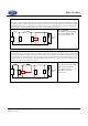
Configuration 2
DUT power circuit "A" remains powered when inductive load is deactivated by SW2. The DUT has an input circuit
"B" that is connected to circuit containing inductive load. Transient pulses A1, A2 and E will be present at "B"
when SW2 opens. Pulse C will be present at "A" if IGN SW remains closed and SW2 opens or bounces Pulses C
and G (load dump) will be present at "A" and "B" when IGN SW and SW2 are closed.
Pulse Application
+
_
SW2
L
W2
BATT
IGN SW
L
W1
L
W1
, L
W2
<< L
R
L
Inductive
Load
Z
3
Z
3
B
Z
2
Z
2
DUTDUT
A
Z
1
Z
1
Apply transient pulse C-1, C-2,
G1, G2 to DUT power connection
"A".
Apply transient pulses
A1, A2-1,
A2-2
, E to DUT input "B".
Apply transient pulse C-1. C-2.
G1, G2 to "A" and "B"
simultaneously