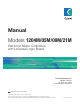
Manual Models 1204M/05M/09M/21M Electronic Motor Controllers with Universal Logic Board Curtis Instruments, Inc. 200 Kisco Avenue Mt. Kisco, NY 10549 www.curtisinstruments.com Read Instructions Carefully! Specifications are subject to change without notice. © 2012 Curtis Instruments, Inc. ® Curtis is a registered trademark of Curtis Instruments, Inc. © The design and appearance of the products depicted herein are the copyright of Curtis Instruments, Inc.
CONTENTS CONTENTS 1. OVERVIEW ................................................................................... 1 2. INSTALLATION AND WIRING ................................................. 3 Mounting the 1204M/05M Controller ..................................... 3 Mounting the 1209M/21M Controller ..................................... 4 Connections: High Current ...................................................... 5 Connections: Low Current........................................................
FIGURES / TABLES FIGURES fig. 1: Curtis 1204M and 1209M electronic motor controllers ............1 fig. 2: Mounting dimensions, Curtis 1204M/05M controllers ............3 fig. 3: Mounting dimensions, Curtis 1209M/21M controllers .............4 fig. 4: Standard wiring configuration, with active main driver .............7 fig. 5: Standard wiring configuration, with active reverse input ..........8 fig. 6: Wiring to inhibit plug braking .................................................9 fig.
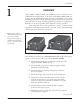
1 — OVERVIEW 1 OVERVIEW Curtis 1204M, 1205M, 1209M, and 1221M series motor controllers are the form/fit/function replacements of the earlier 1204/1205/1209B/1221B controllers, with the added functionality of being programmable—via a Curtis handheld programmer or PC programming station. This means the controllers can be tailored to the needs of specific applications. In addition to configuration flexibility, use of the programmer offers diagnostic and test capability.
1 — OVERVIEW ✓ Plug braking diode internal to controller. ✓ Undervoltage cutback function protects against low battery voltage, including low voltage caused by external loads. ✓ Easily programmable through the Curtis handheld programmer or PC programming station. Familiarity with your Curtis 1204M/05M/09M/21M controller will help you install and operate it properly. We encourage you to read this manual carefully. If you have questions, please contact the Curtis office nearest you.
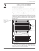
2 — INSTALLATION & WIRING 2 INSTALLATION AND WIRING MOUNTING THE CONTROLLER The outline and mounting hole dimensions are shown for the 1204M and 1205M controllers in Figure 2, and for the 1209M and 1221M controllers in Figure 3. The controllers meet the IP54 requirements for environmental protection against dust and water.
2 — INSTALLATION & WIRING Fig. 3 Mounting 7.2 dia. 22.8 ×19 ×5 25 × 19 × 5 A2: B+ 180 dimensions, Curtis 1209M and 1221M motor controllers. 165 B- 8.5 dia. push-on terminal, 4 plcs MODEL 1209M: MODEL 1221M: 152.4 203 229 281 5.0 M- 80 MODEL 1209M: MODEL 1221M: These controllers contain ESD-sensitive components. Use appropriate precautions in connecting, disconnecting, and handling the controller. See installation suggestions in Appendix A for protecting the controller from ESD damage.
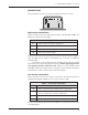
2 — INSTALLATION & WIRING: Connections CONNECTIONS The controller’s connectors are all conveniently located on one end: J1 J2 J3 B– B+ M– J5 A2 J4 High current connections These controllers have four high-current busbars: B+, B-, A2, and M-. The busbars are tin-plated solid copper. Table 1 High Current Connections B+ Battery+ and motor armature. (plug diode -) B- B-. A2 Motor armature and field (plug diode +). M- Motor field (controller output).
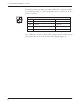
2 — INSTALLATION & WIRING: Connections The mating connector for J4 is a 4-pin Molex Mini-fit Jr. or equivalent. Either an external Status LED or a Curtis programmer can be connected to J4. The pinout is as follows. Table 3 4 2 1 3 J4 J4 Connector Pinout PIN PROGRAMMER STATUS LED J4-1 Data input from programmer (Rx). Status LED enable. J4-2 Ground. Ground. J4-3 Data output to programmer (Tx). Status LED output. J4-4 +15 V. +15 V.
2 — INSTALLATION & WIRING: Standard Wiring Diagrams CONTROLLER WIRING: BASIC CONFIGURATIONS Two basic wiring diagrams are shown; they are identical except for the wiring at terminal J5. In the configuration in Figure 4, the main contactor driver is active. In the configuration in Figure 5, the reverse input is active. Wiring with active main contactor For this option, set the Rev Input / Main Driver parameter = 2 (see page 24), and wire the controller as shown in Figure 4.
2 — INSTALLATION & WIRING: KSI Wiring POLARITY PROTECTION DIODE PEDAL MICROSWITCH INTERLOCKS MAIN Resistor Values 12V: 33 Ω, 5W PRECHARGE RESISTOR 24V: 100 Ω, 10 W 36–48V: 250 Ω, 10W 60–72V: 250 Ω, 20W A2 MOTOR ARMATURE F – S1 MOTOR FIELD F 5kΩ THROTTLE R R F A1 REVERSE + R MAIN POWER WIRING FUSE KEYSWITCH FORWARD CONTROL WIRING FUSE S2 STATUS LED J1 J2 J3 M– B– B+ J5 A2 J4 Fig. 5 Basic wiring diagram, Curtis 1204M/05M/09M/21M with active reverse input.
2 — INSTALLATION & WIRING: Forward/Reverse Wiring Interlocks (seat switches, battery charger interlocks, etc.) should be wired in series so that they turn off the controller KSI and the contactors. Forward/Reverse Wiring With these controllers, it is essential that the field be reversed and that the armature be connected directly to the controller’s B+ and A2 terminals, because the plug diode inside is connected to these terminals; this is the wiring shown in Figures 4 and 5.
2 — INSTALLATION & WIRING: Throttle Wiring Wiring for mechanical reversing switch (golf car type) As shown in Figure 7, this type of switch mechanically interchanges the two motor field cables by rotating a movable contact bar. The configuration shown is typical; many variations are in use. Fig. 7 Wiring for reversing FUSE with a mechanical F/R switch arm.
2 — INSTALLATION & WIRING: Throttle Wiring Some potboxes have a built-in microswitch, eliminating the need to install a separate pedal-actuated microswitch. It is important that a pedal microswitch be included in the circuit as shown in Figures 4 and 5 to allow the microcontroller a few milliseconds to boot up, run diagnostics and safety checks, and then be ready in standby before receiving the throttle signal. A potbox makes it easy to retain the vehicle’s original cable throttle pedal.
2 — INSTALLATION & WIRING: Throttle Wiring Throttle Type 2 With Type 2 throttles, the controller looks for a voltage signal at J3. Zero throttle request corresponds to 0 V and full throttle request to 5 V. A variety of devices can be used with this throttle input type, including voltage sources, current sources, and electronic throttles. The wiring for each is slightly different, as shown in Figure 10, and they have varying levels of throttle fault protection.
2 — INSTALLATION & WIRING: Throttle Wiring Fig. 10 Wiring for Type 2 Voltage Source throttles.
2 — INSTALLATION & WIRING: Throttle Wiring; Pump Applications Basic Wiring Configuration for Pump Applications The 1204M-6302 controller has only three busbars; it is appropriate for use with pump motors, wired as shown in Figure 11. CONTROL WIRING FUSE POWER WIRING FUSE KEYSWITCH ENABLE INTERLOCKS POLARITY PROTECTION DIODE MAIN MAIN PRECHARGE RESISTOR (250 Ω, 5 W) + A1 MOTOR ARMATURE – 5kΩ THROTTLE A2 S1 MOTOR FIELD STATUS LED J1 J2 J3 S2 B– B+ J5 M– J4 Fig.
2 — INSTALLATION & WIRING: Installation Checkout INSTALLATION CHECKOUT Carefully complete the following checkout procedure before operating the vehicle. If a step does not test correctly, refer to Section 5: Diagnostics and Troubleshooting. ☞ Put the vehicle up on blocks to get the drive wheels off the ground before beginning these tests. C AU T I O N Don’t let anyone stand in front of or behind the vehicle during the checkout.
2 — INSTALLATION & WIRING: Installation Checkout G. Take the vehicle down off the blocks and drive it in a clear area. It should have smooth acceleration and good top speed. H. On vehicles that are intended to plug brake, test the plug braking by driving forward at moderate speed and shifting into reverse without letting up on the throttle. The vehicle should smoothly brake to a stop and accelerate in reverse. I.
3 — PROGRAMMABLE PARAMETERS 3 PROGRAMMABLE PARAMETERS The 1204M/05M/09M/21M controllers have a number of parameters that can be adjusted using a Curtis programming device. These programmable parameters allow the vehicle’s performance to be customized to fit the needs of specific applications. The programmable parameters are displayed in five submenus within the Program menu (on the 1311 handheld programmer) or the Parameters menu (on the 1313 handheld programmer or 1314 PC Programming Station).
3 — PROGRAMMABLE PARAMETERS: Voltage Parameters VOLTAGE MENU PARAMETER ALLOWABLE RANGE Battery Voltage 1–6 Under Voltage Cutback Under Voltage Cutback Rate Under Voltage Cutoff 18 DESCRIPTION Set this parameter to match the battery pack of your vehicle. 1 = 12 V 2 = 24 V 3 = 36 V 4 = 48 V 5 = 60 V 6 = 72 V. 68 – 100 % The controller’s circuitry requires a minimum battery voltage to function properly.
3 — PROGRAMMABLE PARAMETERS: Current Parameters CURRENT MENU PARAMETER ALLOWABLE RANGE DESCRIPTION Main Current Limit 50 A – rated current The main current limit can be programmed, in 5A increments, up to the controller’s 2-minute current rating (see model chart in Appendix C). Plug Current Limit 50 – 250 A Plug braking occurs when the opposite direction is selected with the forward/reverse switch without releasing the throttle.
3 — PROGRAMMABLE PARAMETERS: Speed Parameters SPEED MENU PARAMETER ALLOWABLE RANGE DESCRIPTION Accel Rate 0.2 – 3.0 s The Accel Rate defines the time it takes the controller to accelerate from 0% output to 100% output when full throttle is applied. Larger values represent a longer acceleration time and therefore a gentler start. For faster starts, adjust the Accel Rate to a smaller value. Quick Start 0.2 – 3.0 s When the throttle is moved from zero rapidly, the quick start feature is activated.
3 — PROGRAMMABLE PARAMETERS: Throttle Parameters THROTTLE MENU PARAMETER Throttle Type ALLOWABLE RANGE 0–9 DESCRIPTION The 1204M/05M/09M/21M controllers accept a variety of throttle inputs. The Throttle Type parameter can be programmed as follows: 0 1 2 3 4 5 6 7 8 9 Throttle Deadband 2-wire potentiometer, 0–5kΩ input 2-wire potentiometer, 5kΩ–0 input single-ended 0–5V input 2-wire potentiometer, 4.6kΩ–0 input 2-wire potentiometer, 5.5kΩ–0 input 2-wire potentiometer, 1kΩ–0 input ITS input 6.3–10.
3 — PROGRAMMABLE PARAMETERS: Throttle Parameters The Throttle Deadband, Throttle Max, and Throttle Map parameters work together to condition the throttle command, as shown in Figure 12. Fig. 12 Effect of throttle adjustment parameters. Deadband = 10% Throttle Max = 80%. THROTTLE COMMAND (percentage of Max Speed) In the examples shown in this figure, Throttle Max adjusts this endpoint. 100 MAP Map adjusts the “knee” in the output; this knee is at an 80% Map setting.
3 — PROGRAMMABLE PARAMETERS: Misc. Parameters MISCELLANEOUS PARAMETERS PARAMETER ALLOWABLE RANGE DESCRIPTION HPD On/Off By preventing the vehicle from being turned on with the throttle applied, the HPD feature ensures the vehicle starts smoothly and safely. To start, the controller must receive an input to KSI before receiving a throttle input.
3 — PROGRAMMABLE PARAMETERS: Misc. Parameters MISCELLANEOUS PARAMETERS, continued PARAMETER Rev Input / Main Driver ALLOWABLE RANGE 0–2 DESCRIPTION This parameter determines the signal input at the controller’s J5 terminal; see basic wiring diagrams, Figures 4 and 5. 0 = reverse input and main driver both inactive; use this setting if you are replacing an earlier model with no J5 terminal and want to leave the wiring as it was. 1 = Reverse input active (see page 7 description, and Figure 5).
4 — MONITOR MENU 4 MONITOR MENU Through its Monitor menu, the programmer provides access to real-time data during vehicle operation. This information is helpful during diagnostics and troubleshooting, and also while adjusting programmable parameters. MONITOR MENU VARIABLE DISPLAY UNITS Heatsink Temp °C Heatsink temperature. Throttle % Throttle request, as percentage of full throttle. Duty Cycle % Controller’s PWM output, as percentage of programmed Max Speed.
5 — DIAGNOSTICS & TROUBLESHOOTING 5 DIAGNOSTICS AND TROUBLESHOOTING The 1204M/05M/09M/21M controllers detect a wide variety of faults or error conditions. Fault information can be obtained in either of two ways: (1) by observing the fault codes issued by the external Status LEDs or (2) by reading the display on a programmer. Because the programmer uses the same connector as the Status LED, only one of these ways can be used at any given time.
5 — DIAGNOSTICS & TROUBLESHOOTING PROGRAMMER DIAGNOSTICS The programmer’s Faults menu (1311 programmer) / Diagnostics menu (1313 programmer) displays the faults that are currently set, by name. The programmer’s Monitor menu displays various readouts that can be helpful during diagnostics; see Section 4. For example, in the event of an undervoltage cutback fault, the words Undervoltage Cutback will be displayed in the Faults/Diagnostics menu.
5 — DIAGNOSTICS & TROUBLESHOOTING Table 5 TROUBLESHOOTING CHART PROGRAMMER LCD DISPLAY LED CODE EFFECT OF FAULT RECOVERY POSSIBLE CAUSE 1,1 EE Fault PWM output disabled. Modify any programmable 1. EEPROM data lost or parameter with programmer. damaged. 2. EEPROM checksum error. 1,2 MOSFET Short Fault PWM output disabled. Cycle KSI. 1. MOSFET shorted. 1,4 Wiring Fault PWM output disabled. Cycle KSI. 1. HPD Lockout exists for more than 10 seconds.
5 — DIAGNOSTICS & TROUBLESHOOTING Table 5 TROUBLESHOOTING CHART, continued LED CODE PROGRAMMER LCD DISPLAY EFFECT OF FAULT RECOVERY POSSIBLE CAUSE 4,3 Thermal Cutback Output current reduced. 1. Current reduced during 1. Temperature ≥Temp Cutback overtemperature. setpoint or ≤ -10°C. 2. Current reduced to 50% 2. Excessive load on motor or during undertemperature. controller. 3. Improper mounting of controller. 4. Operation in extreme environments. 5. Controller thermistor damaged.
6 — MAINTENANCE 6 MAINTENANCE There are no user serviceable parts in Curtis 1204M/05M/09M/21M controllers. No attempt should be made to open, repair, or otherwise modify the controller. Doing so may damage the controller and will void the warranty. It is recommended that the controller and connections be kept clean and dry and that the controller’s fault history file be checked and cleared periodically.
APPENDIX A: EMC & ESD DESIGN CONSIDERATIONS APPENDIX A VEHICLE DESIGN CONSIDERATIONS REGARDING ELECTROMAGNETIC COMPATIBILITY (EMC) AND ELECTROSTATIC DISCHARGE (ESD) ELECTROMAGNETIC COMPATIBILITY (EMC) Electromagnetic compatibility (EMC) encompasses two areas: emissions and immunity. Emissions are radio frequency (RF) energy generated by a product. This energy has the potential to interfere with communications systems such as radio, television, cellular phones, dispatching, aircraft, etc.
APPENDIX A: EMC & ESD DESIGN CONSIDERATIONS Conducted paths are created by the wires connected to the controller. These wires act as antennas and the amount of RF energy coupled into them is generally proportional to their length. The RF voltages and currents induced in each wire are applied to the controller pin to which the wire is connected. Curtis controllers include bypass capacitors on the printed circuit board’s throttle wires to reduce the impact of this RF energy on the internal circuitry.
APPENDIX A: EMC & ESD DESIGN CONSIDERATIONS Given the safety considerations involved in connecting electrical components to the chassis or frame in battery powered vehicles, such filtering will usually consist of a series inductor (or ferrite bead) rather than a shunt capacitor. If a capacitor is used, it must have a voltage rating and leakage characteristics that will allow the end product to meet applicable safety regulations.
APPENDIX B: PROGRAMMING DEVICES APPENDIX B PROGRAMMING DEVICES Curtis programmers provide programming, diagnostic, and test capabilities for the 1204M/05M/09M/21M controllers. The power for operating the programmer is supplied by the host controller via a 4-pin connector. When the programmer powers up, it gathers information from the controller. Two types of programming devices are available: the PC Programming Station and the handheld programmer.
APPENDIX C: SPECIFICATIONS APPENDIX C SPECIFICATIONS: 1204M/05M/09M/21M CONTROLLERS Nominal input voltage PWM operating frequency Electrical isolation to heatsink (min.) Model specific (see below): 24 – 36 V, 36 – 48 V, 48 – 72 V, 60–72 V 15.6 kHz 24 – 36 V and 36 – 48 V models: 500 VAC 48 – 72 V and 60 – 72 V models: 1000 VAC KSI input current (no contactors engaged) 70 mA without programmer; 130 mA with programmer Logic input current < 2 mA Status LED output current (max.