
Specifications


Curtis 1204M/1205M/1209M/1221M Manual
11
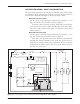
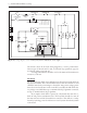
Some potboxes have a built-in microswitch, eliminating the need to install
a separate pedal-actuated microswitch. It is important that a pedal microswitch
be included in the circuit as shown in Figures 4 and 5 to allow the microcon
-
troller a few milliseconds to boot up, run diagnostics and safety checks, and
then be ready in standby before receiving the throttle signal.
A potbox makes it easy to retain the vehicle’s original cable throttle pedal.
Curtis and various third-party vendors also offer self-contained footpedal units
that eliminate the need for fabricating and installing a pedal-potbox linkage.
Any potbox that can provide a nominal 0–5kΩ output will work as a Type 0
throttle input.
If a potbox is used, it must be mounted so as to allow connection be
-
tween the potbox lever arm and the vehicle accelerator linkage. Use of a second
return spring on the pedal, in addition to the potbox return spring, is required
to prevent an uncontrollable full-on throttle input (which could happen if
there was a single spring, and it broke). If the self-contained potbox spring is
insufficient to return the pedal by itself, two additional pedal return springs
must be used.
It is also required that the accelerator pedal hit a mechanical stop at its
full-on position just before (≈1 mm) the potbox lever hits its own full-on stop.
This mechanical stop will prevent the potbox lever arm from bending if undue
force is put on the pedal. Protection of the potbox from water and dirt will
help avoid problems of corrosion and electrical leakage.
After the potbox has been mounted, operation of the pot can be tested
by measuring the resistance between the two wires with an ohmmeter. With
the pedal not applied, the resistance should be less than 50 ohms. As the pedal
is applied, the resistance should rise smoothly until it reaches a value between
4500 and 5500 ohms. Values below 4500 ohms may cause a reduction in
efficiency and top speed; however, you still can get top speed by lowering the
Throttle Max setting. Values above 7500 ohms indicate a defective potbox, and
will cause controller shutdown.
Throttle Types 1, 3, 4, 5
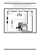
Wiring for Type 1, 3, 4, and 5 throttles is the same as for Type 0 throttles;
again, it doesn’t matter which wire goes on which terminal. With these throttles,
resistance is in an inverse relationship to applied throttle; that is, resistance
decreases as applied throttle is increased.
2 — INSTALLATION & WIRING: Throttle Wiring
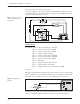
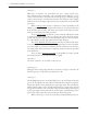
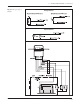
Fig. 9 Wiring for Type 1,
3, 4, and 5 throttles.
J1
J2
J3
5kΩ–0
(Type 1)
4.6kΩ–0
(Type 3)
5.5kΩ–0
(Type 4)
1kΩ–0
(Type 5)
FASTER