
Use and Care Manual


7
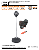
MODEL# 9308TS
12
4
3
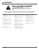
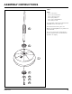
ASSEMBLY INSTRUCTIONS
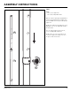
STEP 3:
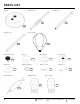
Parts:
Part 4 (x1) - Upper Pole
Part 12 (x1) - Adjustable Knob
With the smaller opening facing upwards to
install the Speed Bag, slide the Upper Pole
(4) to the Middle Pole until you find a proper
height size.
NOTE: Every indent on the Upper Pole is an
appropriate size for the Adjustable Knob to
be installed on.
Once the right height has been chosen,
secure the Adjustable Knob (12).
NOTE: Failure to secure in an indent can
scratch the Upper Pole and/or can cause
the pole to slide off the Base.