
Use and Care Manual


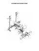


STEP 2: ASSEMBLE CENTER SUPPORT FRAME
Locate: Control Brace (8), Front Leg (2), Support Plate (18), Flat Plate (13), 2x M10*60 Bolts (32), 1x M8*55 Bolt (34), 4x M8*16
Bolts (35), 4x M10 Washers (37), 6x M8 Washers (38), 2x M10 Nuts (39), 1x M8 Nut (40), 1x Preacher Curl Sleeve (29), 3x Rectan-
gular End Caps (24), 4x Square End Caps 2 (26)
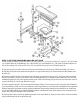
A. Thread one M10 Washer (37) on each of the two M10*60 Bolts (32). Thread these bolts through the Flat Plate (13). Line up the
Control Brace (8) to the two holes in the Support Tube (4). Place the Flat Plate on the rear outer surface of the Support Tube lined
up to the holes in the center. Place the M10 Bolts through this tube and into the Control Brace. Secure the Flat Plate to the Control
Brace with 2x M10 Washers (37) and 2x M10 Nuts (39).
B. Place the Front Leg (2) into the open end of the Control Brace (8). Secure the Front Leg to the Control Brace using the three pre-
drilled holes in the top and the sides of the Control Brace using 3x M8 Washers (38) and 3x M8*16 Bolts (35).
C. Place the Support Plate (18) against the vertical post on the Front Leg and secure with 1x M8 Washer and 1x M8*16 Bolt (35).
Place the opposite end of the Support Plate against the underside of the Control Brace (8) and connect by placing 1x M8*55 Bolt
(34) and M8 Washer (38) combination down through the Control Brace Tube. Connect this to the underside of the Control Brace us-
ing another M8 Washer and the M10 Nut (40).
D. Place the Preacher Curl Sleeve (29) into the opening at the top of the Front Leg (2). Place 3x Rectangular End Caps (24) into the
open ends at the bottom of the Front Leg. Place 4x Square End Caps (26) into the open ends of the two welded bars near the end of
the Control Brace (8).