FID WEIGHT BENCH MODEL# 8639FID PRODUCT MANUAL - VERSION 08.17.06 FOR AGES: 13+ WEIGHT LIMIT: 400 Lbs 181 Kgs ADULT(S) NEEDED: TOOLS NEEDED: WARNING/ADVERTENCIA CUSTOMER SERVICE • Do not allow more than one person on the bench at a time. • The contents of this package are not suitable for children under 3 years old. GQBrands.com • Consult a physician before beginning any exercise program or strenuous activity. • Contains small parts which may cause choking. CustomerService@GQBrands.
CUSTOMER SERVICE INFORMATION Thank you for purchasing: FID WEIGHT BENCH MODEL# 8639FID At Global Quality Brands®, we want all of our customers to be completely satisfied with their purchase. Please take time to review the contents of the product you have just received to make sure that all of the parts are included. If you find that any parts are missing or damaged, we will happily provide replacement parts at no charge within 30 days of purchase.
LIMITED WARRANTY Global Quality Brands® warrants this product to be free from defects in workmanship and materials under normal use and conditions for a period of 90 DAYS FROM THE DATE OF ORIGINAL PURCHASE. This Limited Warranty is not transferable and is available only for the original purchaser of the Product. The Company’s obligation under this warranty is limited to replacing or repairing the Product, at the discretion of the company.
WARNINGS IMPORTANT MESSAGE WARNING - PLEASE READ ADULT ASSEMBLY REQUIRED CHOKING HAZARD - Small Parts NOT for children under 3 years of age. WARNING: While every attempt is made to ensure the highest degree of protection in all equipment, we cannot guarantee freedom from injury. The user assumes all risks of injury due to use. All merchandise is sold on this condition, which no representative of the company can waive or change. 4 GQBrands.com CustomerService@GQBrands.
WARNINGS Please read these warnings and the information in this manual in its entirety. Failure to comply with the following instructions may increase the risk of serious injury and/or death: • Ensure that this product has been assembled correctly, per the instructions in the manual. • DO NOT make any modifications to this equipment or use this machine in any manner it is not intended for. • This manual is designed to help you assemble, adjust, maintain and use the product.
PARTS LIST VIEW 1 - Main Frame 2 - Front Leg Base x1 x1 3 - 2” Square End Cap x3 6 - Slide Collar 5 - M10 x 15 Bolt 4 - M10 Washer x17 x3 x1 7 - Pop Pin 9- 8 - Back Base Leg Caps x2 x1 10 - 1” Square End Cap x1 x8 12 - M10 x 75mm 11 - Support Cannulation 13 - M10 Nut x7 x1 x1 15 - M10 x 150mm 14 - Back Rest Support 16 - Leg Lift x1 x2 6 x1 GQBrands.com CustomerService@GQBrands.
PARTS LIST 17 - M10 x 70mm 18 - 1” Round Bumper x2 19 - Spring Clip x1 x1 23 - M8 Washer 22 - Foam Roller 21 - Leg LIft Tube Rod 20 - 1” Round Bumper x7 24 - M8 x25mm x8 x3 x8 x6 26 - Back Cushion 25 - Seat Cushion 27 - 2” Round Cap 28 - M10 x 30mm x2 x1 x2 x1 29 - M10 x 85mm x2 31 - Leg Lift Weight Tube 30 - Front Leg Support x1 x1 MODEL# 8639FID 7
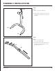
ASSEMBLY INSTRUCTIONS STEP 1: Parts: Part 2 (x1) - Front Leg Base Part 30 (x1) - Front Leg Support (30) Align the Front Leg Base so the bottom bracket openings match with the opendins of the Front Leg Base.
ASSEMBLY INSTRUCTIONS (3) STEP 3: Parts: Part 3 (x3) - Square End Cap A. If all 3 Square end Caps ( Part 3) are not alread installed, push in their respective openings. (3) (3) STEP 4: Parts: Part 1 (x1) - Main Frame Part 6 (x1) - Slide Collar from the bottom of the Main Frame (Part 1), slide the Slide Collar (Part 6) to an opening of your choice.
ASSEMBLY INSTRUCTIONS STEP 5: Parts: Part 7 (x1) - Pop Pin Part 6 (x1) - Slide Collar Once you have aligned the SLide Collar to an opening of your choice, Grab the Pop Pin (Part 7) and twist to secure the Pop Pin to the opening (6) (7) STEP 6: To adjust the Slide Collar position in the Main Frame, pull the Pop Pin handle towards you and keep it pulled as you slide the collar to a preffered opening. Once you are ready to secure the Slide Collar, release the Pop Pin and secure to that opening.
ASSEMBLY INSTRUCTIONS STEP 7: Align the openings of the Main Frame to the openings of the Front Leg Support bar. Make sure that the bottom half of the Main Frame is aiming at the floor to make sure both bars align properly. STEP 8: Parts: Part 4 (x4) - M10 Washer Part 13 (x2) - M10 Nut Part 28 (x2) - M10 x 30mm Secure the Main Fraime and the Front Leg Support Bar by using a M10 x 30mm (Part 28) bolt, 2x M10 washers (Part 4), and a M10 Nut (Part 13) on both openings.
ASSEMBLY INSTRUCTIONS STEP 9: Parts: Part 8 (x1) - Back Base locate the opening at the bottom of the Main Frame, and push the Back Base (Part 8) so all 3 openings align properly for the INstalatio of Step 10 (8) STEP 10: Parts: Part 5 (x3) - M10 x 15mm Bolt Part 23 (x3) -M8 Washers (5) (5) (23) Secure all 3 openings by installing 3x M10 15mm Bolts (Part 5) with M8 washers (Part 23) (23) (23) (5) 12 GQBrands.com CustomerService@GQBrands.
ASSEMBLY INSTRUCTIONS STEP 11: Parts: Part 9 (x2) - Leg Caps (9) Once the Back Base is installed onto the Main Frame. Place a Leg Cap (Part 9) on each side of the Base to prevent the base from sliding. (9) STEP 12: Parts: Part 4 (x2) - M8 Washers Part 11 (x1) - Support Cannulation Part 12 (x1) - M10 x 75mm Part 13 (x1) - M10 Nut Place the bottom section of the Support Cannulation (Part 11) between both openings of the Slide Collar.
ASSEMBLY INSTRUCTIONS STEP 13: Parts: Part 4 (x2) - M10 Washer Part 13 (x1) -M10 Nut Part 14 (x2) -Back Rest Support Part 15 (x1) - M10 x 150mm (14) (14) Align the openings from the Back Rest Support (Part 14) to their respective tubes. Middle openings to the upper part of the Support Cannulation, and bottom openings to the Main Frame. Secure to the Cannulation by using the M10 x 150mm (Part 15) bolt, with M10 Washers (Part 4), and tighten with M10 Nut (Part 13) (13) (4) (4) (15) 14 GQBrands.
ASSEMBLY INSTRUCTIONS STEP 14: Parts: Part 16 (x1) - Leg Lift Part 19 (x1) - Spring Clip Part 20 (x1) - Round Bumper Part 27 (x2) - 2” Round Cap Part 31 (x1) - Leg Lift Weight Tube (27) To install the Leg Lift (Part 16) to the Front Leg Support, all additional parts must be installed. (16) (20) (19) (31) Make sure both 2 “ Round Caps (Part 27) are insterted to both tube openings. Insert the Leg Lift Weight Tube (Part 31) and secure with the Spring Clip (Part 19).
ASSEMBLY INSTRUCTIONS STEP 16: Parts: Part 23 (x8) - M8 Washer Part 24 (x8) - M8 x 25mm Part 25 (x1) - Seat Cushion Part 26 (x1) - Back Cushion Align the openings from the back of the Seat Cushion (Part 25) to the openings of the Main Frame. (26) Align the openings from the back of the Back Cushion (Part 26) to the openings of the Back Rest Support. (25) Secure all 8 openings by using all M8 x 25mm (Part 24) bolts and M8 Washers (Part 23) untill both Cushions are secure. (23) (24) 16 GQBrands.
ASSEMBLY INSTRUCTIONS NOTE: 2 Knee Heights There are two heights to place the Leg Lift Tube Rod (Part 21) You may switch the position of the tube depending on the your height and comfort while working out on the bench. STEP 16: Parts: Part 20 (x6) - M8 Washer Part 21 (x8) - M8 x 25mm (21) (20) (21) Align the openings from the back of the Back Cushion (Part 26) to the openings of the Back Rest Support.
ASSEMBLY INSTRUCTIONS STEP 17: (22) Parts: Part 22 (x6) - Foam Roller (22) Place all x6 Foam Rollers on the Lef Lift Tube Rods. (22) (22) (22) (22) 18 GQBrands.com CustomerService@GQBrands.
PINCH POINTS & WARNINGS LOCATION MODEL# 8639FID 19
FREQUENTLY ASKED QUESTIONS • Question: "Is there any maintenance I need to do for my Bench?" Answer: Before each use, you should always double check to make sure all your bolts are tight and secure, the adjustable components and cushions are securely attached and/or locked, and there is no damage to the frame or its parts. If any of the conditions are found, tighten bolts and/or secure any adjustable components.