Technical Information Deltabar M PMD55 Differential pressure measurement Differential pressure transmitter with metal sensor Communication via HART, PROFIBUS PA or FOUNDATION Fieldbus Application Your benefits The Deltabar M differential pressure transmitter is used for the following measuring tasks: • Flow measurement (volume or mass flow) in conjunction with primary elements in gases, vapours and liquids • Level, volume or mass measurement in liquids • Differential pressure monitoring, e.g.
Deltabar M PMD55 Table of contents Function and system design. . . . . . . . . . . . . . . . . . . . . 3 Measuring principle . . . . . . . . . . . . . . . . . . . . . . . . . . . . . . . . . . . 3 Level measurement (level, volume and mass) . . . . . . . . . . . . . . . . 3 Flow measurement . . . . . . . . . . . . . . . . . . . . . . . . . . . . . . . . . . . . 4 Communication protocol . . . . . . . . . . . . . . . . . . . . . . . . . . . . . . . 6 Input . . . . . . . . . . . . . . . . . . . . . . . . . .
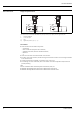
Deltabar M PMD55 Function and system design Measuring principle 2 3 1 p1 4 p2 P01-PMD55xxx-03-xx-xx-xx-001 Measuring cell of the Deltabar M 1 2 3 4 Sensing element Overload diaphragm/Middle diaphragm Filling oil Process isolating diaphragm The separating diaphragms (4) are deflected on both sides by the acting pressures p1 and p2. A filling oil (3) transfers the pressure to a resistance circuit bridge (semi-conductor technology).
Deltabar M PMD55 Flow measurement Design and operation mode 1 1 2 2 + Q ~ Dp p1 – p2 Q + Q ~ Dp p1 – p2 Q P01-PMD55xxx-15-xx-xx-xx-001 Flow measurement with Deltabar M PMD55 and primary element, left: Orifice plate and right: Pitot tube 1 2 Q p Deltabar M PMD55 3-valve manifold Flow Differential pressure, p = p1 – p2 Your benefits • Choice between five flow modes of operation: – Volume flow – Norm volume flow (European norm conditions) – Standard volume flow (American standard conditions
Deltabar M PMD55 Typical arrangements for flow measurements A B C PMD55, V1 PMD55, H1 PMD55, V1 P01-PMD55xxx-11-xx-xx-xx-011 A: liquid in vertical pipe; H1 version; horizontal impulse line; alignment 180° B: gas in horizontal pipe; V1 version; vertical impulse line; alignment 90° C: steam in horizontal pipe; V1 version; vertical impulse line; alignment 90° Mounting example 2 2 1 1 PMD55, V1 PMD55, V1 P01-PMD55xxx-11-xx-xx-xx-014 1: Valve manifold 2: Impulse line Endress+Hauser 5
Deltabar M PMD55 Communication protocol 6 • 4 to 20 mA with HART communication protocol • PROFIBUS PA – The Endress+Hauser devices meet the requirements of the FISCO model. – Due to the low current consumption of 11 mA ± 1 mA, the following number of devices can be operated on one bus segment if installing as per FISCO: – up to 8 Deltabar M for Ex ia, CSA IS and FM IS applications – up to 31 Deltabar M for all other applications, e.g. in non-hazardous areas, Ex nA, etc.
Deltabar M PMD55 Input Measured variable Differential pressure, from which flow (volume or mass current) and level (level, volume or mass) are derived. Measuring range Nominal value Measurement limit Smallest span MWP2 (factory calibration)1 OPL3 Min. operating pressure4 on one side on both sides Version in the Order Code5 Feature 070 lower (LRL) upper (URL) [mbar (psi)] [mbar (psi)] [mbar (psi)] [mbar (psi)] 10 (0.15) –10 (– 0.15) +10 (+ 0.15) 0.5 (0.0075) 30 (0.45) –30 (– 0.
Deltabar M PMD55 Explanation of terms Explanation of the terms: Turn down (TD), set span and zero based span Case 1: • Lower range value Upper range value Example: • Lower range value (LRV) = 0 mbar • Upper range value (URV) = 100 mbar (1.5 psi) • Nominal value (URL) = 500 mbar (7.5 psi) ➀=➁ LRL LRV URV URL –500 mbar 0 100 +500 mbar ➂ Turn down: • TD = URL /URV5:1 ➃ set span: • URV – LRV = 100 mbar (1.5 psi) This span is based on the zero point.
Deltabar M PMD55 Output Output signal • 4 to 20 mA with superimposed digital communication protocol HART 6.0, 2-wire • Digital communication signal PROFIBUS PA (Profile 3.02) • Digital communication signal FOUNDATION Fieldbus Signal range – 4 to 20 mA HART 3.8 mA to 20.5 mA Signal on alarm As per NAMUR NE 43 • 4 to 20 mA HART Options: – Max. alarm*: can be set from 21...23 mA (factory setting: 22 mA) – Keep measured value: last measured value is kept – Min. alarm: 3.
Deltabar M PMD55 Dead time, Time constant I 100 % 90 % 63 % t1 t2 t t3 P01-xxxxxxxx-05-xx-xx-xx-036 Presentation of the dead time and the time constant Dynamic behavior: current output Dead time (t1) [ms] Time constant T63 (= t2) [ms] Time constant T90 (= t3) [ms] 60 90 210 Dead time (t1) [ms] Dead time (t1) [ms] + Time constant T63 (= t2) [ms] Dead time (t1) [ms] + Time constant T90 (= t3) [ms] min. 220 310 370 max. 1020 1110 1170 max.
Deltabar M PMD55 Dynamic behavior: FOUNDATION Fieldbus Dead time (t1) [ms] Dead time (t1) [ms] + Time constant T63 (= t2) [ms] Dead time (t1) [ms] + Time constant T90 (= t3) [ms] min. 105 195 255 max. 1105 1195 1255 Reading cycle • Cyclic: max. 10/s (dependent on the number and type of function blocks used in a closed-control loop) • Acyclic: typical 5/s Cycle time (update time) Cyclic: min. 100 ms Response time • Cyclic: max.
Deltabar M PMD55 Data of the FOUNDATION Fieldbus interface Basic data Device Type 0x1021 Device Revision 01 (hex) DD Revision 0x01021 CFF Revision 0x000102 ITK Version 5.2.0 ITK Certification Driver No.
Deltabar M PMD55 Function blocks Block Content Resource Block The Resource Block contains all the data that uniquely identify the device. It is an electronic version of a nameplate of the device. Number Execution time of blocks Functionality 1 enhanced Analog Input Block 1 Analog Input Block 2 The AI Block receives the measuring data from the Sensor Block, (selectable via a channel number) and makes the data available to other function blocks at its output.
Deltabar M PMD55 Power supply Electrical connection Note! • When using the measuring device in hazardous areas, installation must comply with the corresponding national standards and regulations and the Safety Instructions or Installation or Control Drawings ä 42, section "Safety Instructions" and "Installation/Control Drawings". • According to IEC/EN61010 a suitable disconnector has to be installed for the device. • Devices with integrated overvoltage protection must be earthed.
Deltabar M PMD55 FOUNDATION Fieldbus The digital communication signal is transmitted to the bus via a 2-wire connection. The bus also provides the power supply. For further information on the network structure and grounding and for further bus system components such as bus cables, see the relevant documentation, e.g. Operating Instructions BA00013S "FOUNDATION Fieldbus Overview" and the FOUNDATION Fieldbus Guideline.
Deltabar M PMD55 Devices with M12 plug PIN assignment for M12 connector 4 3 1 + 2 – nc PIN Meaning 1 Signal + 2 Not assigned 3 Signal – 4 Earth A0011175 Endress+Hauser offers the following accessories for devices with an M12 plug: Plug-in jack M 12x1, straight • Material: body PA; coupling nut CuZn, nickel-plated • Degree of protection (fully locked): IP67 • Order number: 52006263 Plug-in jack M 12x1, elbowed • Material: body PBT/PA; coupling nut GD-Zn, nickel-plated • Degree of protectio
Deltabar M PMD55 Supply voltage Note! • When using the measuring device in hazardous areas, installation must comply with the corresponding national standards and regulations and the Safety Instructions or Installation or Control Drawings. • All explosion protection data are given in separate documentation which is available upon request.
Deltabar M PMD55 Performance characteristics Reference operating conditions • • • • • • • • • • • • • As per IEC 60770 and IEC 61298-1, Sections 5 to 7 Ambient temperature TU = constant, in the range of: +21...+33°C (+70...91 °F) Humidity = constant, in the range of: 5...80 % r.H Ambient pressure pU = constant, in the range of: 860...1060 mbar (12.47...15.
Deltabar M PMD55 Influence of the static pressure Measuring cell Influence on zero point Influence on span 10 mbar (0.15 psi) ±0.2 % v. URL / 1 bar ±0.2 % v. URL / 1 bar 30 mbar (0.45 psi) ±0.07 % v. URL / 1 bar ±0.07 % v. URL / 1 bar 100 mbar (1.5 psi) ±0.15 % of URL / 70 bar ±0.14 % of URL / 70 bar 500 mbar (7.5 psi) 1 bar (15 psi) 3 bar (45 psi) 16 bar (240 psi) 40 bar (600 psi) ±0.075 % of URL / 70 bar ±0.
Deltabar M PMD55 Influence of the installation position The recommended maximum angle to the axis of the diaphragm is 10° and results in a measuring error of ±0.72 mbar (0.01 psi). The value is doubled for devices with inert oil. Note! Position-dependent zero shift can be corrected ä 21, section "General installation instructions". ° .10 0.. 0. ..1 0° P01-PMD55xxx-17-xx-xx-xx-001 Vibration effects Warm-up period 20 Test standard Vibration effects GL reference accuracy to 10...
Deltabar M PMD55 Operating conditions (Installation) General installation instructions • The position-dependent zero shift can be corrected directly at the device via operating keys. • Endress+Hauser offers a mounting bracket for installing the device on pipes or walls ä 22, section "Wall and pipe mounting". • When measuring in media with solid proportions, such as dirty liquids, installing separators and drain valves is useful for capturing and removing sediment.
Deltabar M PMD55 Wall and pipe-mounting (optional) Endress+Hauser offers a mounting bracket for installing the device on pipes or walls. A bracket with mounting accessories for pipe mounting is included with the device. Note! When using a valve block, the block's dimensions must be taken into account. 1 0 M1 6 7/1 41 .4 66 .3 2 135 41.3 90 54 60 41.3 54 37.5 6 30 54 6.
Deltabar M PMD55 Typical installation arrangements PMD55, H2 A 1 2 3 3 B 2 1 PMD55, V1 P01-PMD55xxx-17-xx-xx-xx-001 A: Installation for horizontal impulse pipes; H2 version B: Installation for vertical impulse pipes; V1 version 1: Deltabar M; 2: Adapter; 3: Mounting bracket Endress+Hauser 23
Deltabar M PMD55 Oxygen applications Oxygen and other gases can react explosively to oils, grease and plastics, such that, among other things, the following precautions must be taken: – All components of the system, such as measuring devices, must be cleaned in accordance with the BAM (DIN 19247) requirements.
Deltabar M PMD55 Operating conditions (Environment) Ambient temperature range • –40...+85°C (–40 to +185°F) • On-site display: -20 to +70°C (-4 to 158°F) Enhanced temperature range with limitations concerning display speed and contrast: -40 to +85°C (-40 to +185°F) For devices for use in hazardous areas, see Safety instructions, Installation or Control Drawing ä 42, sections "Safety Instruction" and "Installation/Control drawings").
Deltabar M PMD55 Operating conditions (Process) Process temperature limits (temperature at transmitter) • Process connections made of 316L: –40 to +85°C (–40 to +185°F) • Process connections made of C22.8: –10 to +85°C (+14 to +185°F) The process temperature at the transmitter can be reduced through the use of pulse lines. Note! • For oxygen applications, observe ä 24 "Oxygen applications" section. • Observe the Process temperature range of the seal.
Deltabar M PMD55 Mechanical construction Process connection Oval flange, connection 1/4-18 NPT IEC61518 PMD55, H1 PMD55, V1 P01-PMD55xxx-11-xx-xx-xx-015 Designation of the process connections "P1" and "P2" Factory setting • P1: High pressure side (+) • P2: Low pressure side (-) This setting can be changed via a DIP switch in the connection department of the instrument and via the operating menu: on 2 3 4 5 off SW / P2=High 1 P01-PMD55xxx-04-xx-xx-xx-011 DIP switches in the connection compartm
Deltabar M PMD55 66.4 (2.6) Dimensions V1 version; Impulse pipe vertical; alignment 90° 95 (3.7) 15.5 (0.6) 122 (4.8) 75 (3.0) 13 (0.5) 54 (2.1) 104 (4.0) 61 (2.4) M10 7/16 A: 150 (5.9) 116 (4.6) B: 164 (6.5) 41 (1.
Deltabar M PMD55 75 (3.0) 104 (4.0) 61 (2.4) Dimensions H1 version; Impulse pipe horizontal; alignment 180° A: 170 (6.7) 122 (4.8) 116 (4.6) B: 184 (7.
Deltabar M PMD55 66.4 (2.6) Dimensions H2 version; Impulse pipe horizontal; alignment 90° 95 (3.7) 15.5 (0.6) 122 (4.8) 75 (3.0) 13 (0.5) 54 (2.1) 104 (4.0) 61 (2.4) M10 7/16 A: 150 (5.9) 116 (4.6) B: 164 (6.5) 41 (1.
Deltabar M PMD55 Material (not wetted) Housing 14 12 13 11 1 6 8 2 7 10 3 5 4 9 P01-xMxx3xxx-14-xx-xx-xx-002 Front view, right-hand side view, top view. Item number 1 2 Component part Material F30 housing, RAL 5012 (blue) Die-cast aluminum with protective powder-coating on polyester base Die-cast aluminum with protective powder-coating on polyester base EPDM Mineral glass Silicone (VMQ) AISI 304 (1.4301) Plastic film AISI 304 (1.4301)/ AISI 316 (1.
Deltabar M PMD55 Connecting parts 1 2 P01-PMD55xxx-06-09-xx-xx-001 Item number Component part 1 Adapter plate 2 Mounting bracket Material (wetted) Material AISI 304 AISI 304 Screw and nuts A2-70 Side flanges Endress+Hauser supplies side flanges made of stainless steel AISI 316L as per material numbers 1.4435 or 1.4404. With regard to their stability-temperature property, the materials 1.4435 and 1.4404 are grouped together under 13EO in EN 1092-1 Tab. 18.
Deltabar M PMD55 Human interface Local operation Zero ➅ Span 4 R FIELD COMMUNICATION PROTOCOL delta p only 5 ➅ on TM off off FOUNDATION SW HW on off 1 3 damping 2 4 5 ➅ ➆ on off 1 SW / Ö SW / P2=High 3 Display Zero Address damping SW / Alarm min SW / Ö SW / P2=High 2 ➇ on off on 1 ➇ on HART SW / Ö SW / P2=High off ➆ Display 1 2 damp not used 3 off:SW 4 delta p on:Ö only on:P2=High off:SW 5 on damping SW / Alarm min Zero damping simulation SW / Ö SW / P2=Hig
Deltabar M PMD55 Function of the operating keys Note! The operation via the keys on the electronic insert is only possible if the onsite display is not connected.
Deltabar M PMD55 Local display (optional) A 4-line liquid crystal display (LCD) is used for display and operation. The local display shows measured values, dialog texts as well as fault and notice messages in plain text, thereby supporting the user at every stage of operation. The liquid crystal display of the device can be turned in 90° stages. Depending on the orientation of the device, this makes it easy to operate the device and read the measured values.
Deltabar M PMD55 Remote operation All software parameters are accessible depending on the position of the write protection switch on the device. HART Remote operation via: • Field Communicator 375 handheld terminal see "Hardware and software for onsite and remote operation" section ä 37). • FieldCare (see "Hardware and software for onsite and remote operation" section ä 37 ff) with Commubox FXA195 (see "Hardware and software for onsite and remote operation" section ä 37 ff) • Field Xpert.
Deltabar M PMD55 Hardware and software for onsite and remote operation Commubox FXA195 For intrinsically safe HART communication with FieldCare via the USB interface. For details refer to TI00404F/00/EN. Field Communicator 375 With a handheld terminal, all the parameters can be configured anywhere along the bus line via menu operation (HART and FOUNDATION Fieldbus). FieldCare FieldCare is an Endress+Hauser asset management tool based on FDT technology.
Deltabar M PMD55 Certificates and approvals CE mark The device meets the legal requirements of the relevant EC directives. Endress+Hauser confirms that the device has been successfully tested by applying the CE mark. Ex approvals • • • • • ATEX FM CSA NEPSI IECEx All explosion protection data are given in separate documentation which is available upon request. The Ex documentation is supplied as standard with all devices approved for use in explosion hazardous areas.
Deltabar M PMD55 Ordering information PMD55 This overview does not mark options which are mutually exclusive. 010 Approval: AA BA BB BC BD B1 CA CB CC CD C1 FA FB FC FD F1 IA IB ID IE I1 NA NB 8A Non-hazardous area ATEX II 1/2 G Ex ia IIC T6 ATEX II 1/2 D Ex t IIIC ATEX II 2 G Ex d IIC T6 ATEX II 3G Ex nA IIC T6 ATEX II 1/2 G Ex ia IIC T6 + ATEX II 1/2 D Ex iaD CSA C/US IS Cl.I,II,III Div.1 Gr.A-G, CSA C/US IS Cl.I Div.2 Gr.A-D, Ex ia, C: Zone 0,1,2/US: Zone 0,1,2,20,21,22 CSA C/US XP Cl.I,II Div.1 Gr.
Deltabar M PMD55 070 Sensor Nominal Value: 88 Prepared for Deltatop 080 Reference Accuracy: D G Platinum Standard 090 Calibration; Unit: B C D E F J K L 8 Nominal value; mbar/bar Nominal value; kPa/MPa Nominal value; mm/mH2O Nominal value; inH2O/ftH2O Nominal value; psi Customised pressure; see additional spec. Customised level; see additional spec. Customised flow; see additional spec. Adjusted for Deltatop; see additional spec.
Deltabar M PMD55 Additional ordering information (optional) 500 Additional Operation Language: AA AB AC AD AE AF AK AL English German French Spanish Italian Dutch Chinese Japanese 550 Calibration: F1 F2 Works calib. certificate 5-point DKD calib.
Deltabar M PMD55 Additional documentation Technical Information • EMC test procedures TI00241F/00/EN • Cerabar M: TI00436P/00/EN • Deltapilot M: TI00437P/00/EN Operating Instructions • 4 to 20 mA HART: BA00382P/00/EN • PROFIBUS PA: BA00383P/00/EN • FOUNDATION Fieldbus: BA00384P/00/EN Brief operating instruction • 4 to 20 mA HART: KA01027P/00/EN • PROFIBUS PA: KA01028P/00/EN • FOUNDATION Fieldbus: KA01029P/00/EN Safety Instructions Authority Version in the Approval order code Category Electronics
Deltabar M PMD55 Installation/Control Drawings Authority Version in the Approval order code FA Endress+Hauser FM FB CSA CA IS Cl.I,II,III Div.1 Gr. A-G, AEx ia NI Cl. I Div.2 Gr.A-D Electronics Documentation – 4 to 20 mA HART – ZD00234P FM XP Cl.I,II Div.1 Gr.A-G Zone 1 IIC – 4 to 20 mA HART T6 (Conduit seal not required), Zone 1,2 – PROFIBUS PA -– FOUNDATION Fieldbus C/US IS Cl.I,II,III Div.1 Gr A-G C/US IS Cl.I Div.
Deltabar M PMD55 Configuration data sheet Pressure The following configuration data sheet has to be filled in and to be included in the order when the option "J: Customized pressure" has been selected in feature "090: Calibration; Unit" of the product structure.
Deltabar M PMD55 Level The following configuration data sheet has to be filled in and to be included in the order when the option "K: Customized level" has been selected in feature "090: Calibration; Unit" of the product structure.
Deltabar M PMD55 Flow The following configuration data sheet has to be filled in and to be included in the order when the option "L: Customized flow" has been selected in feature "090: Calibration; Unit" of the product structure.
Deltabar M PMD55 Endress+Hauser 47
Deltabar M PMD55 Instruments International Endress+Hauser Instruments International AG Kaegenstrasse 2 4153 Reinach Switzerland Tel. +41 61 715 81 00 Fax +41 61 715 25 00 www.endress.com info@ii.endress.com TI00434P/00/EN/15.11 71128311 CSS/FM+SGML 6.