2670 Denali OWNER’S MANUAL FISHING BOATS 3901 St. Lucie Blvd. Ft.
THIS PAGE WAS LEFT BLANK INTENTIONALLY 2 2670 Denali
SAFETY INFORMATION Your Owner’s Manual has been written to include a number of safety instructions to assure the safe operation and maintenance of your boat. These instructions are in the form of DANGER, WARNING, CAUTION, and NOTICE statements. The following definitions apply: IMMEDIATE HAZARDS WHICH WILL RESULT IN SEVERE PERSONAL INJURY OR DEATH. HAZARDS OR UNSAFE PRACTICES WHICH COULD RESULT IN SEVERE PERSONAL INJURY OR DEATH.
THIS PAGE WAS LEFT BLANK INTENTIONALLY 4 2670 Denali
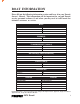
BOAT INFORMATION Please fill out the following information section and leave it in your Pursuit Owner’s Manual. This information will be important for you and Pursuit service personnel to know, if and when you may need to call Pursuit for technical assistance or service.
THIS PAGE WAS LEFT BLANK INTENTIONALLY 6 2670 Denali
CERTIFICATIONS & SPECIFICATIONS (For Export Only) To be in compliance with European directives for recreational boats as published by the International Organization for Standardization (ISO) in effect at the time this boat was manufactured, we are providing the following information.
THIS PAGE WAS LEFT BLANK INTENTIONALLY 8 2670 Denali
IMPORTANT INFORMATION Warranty and Warranty Registration Cards The Pursuit Limited Warranty Statement is included with your boat. It has been written to be clearly stated and easily understood. If you have any questions after reading the warranty, please contact Pursuit Customer Relations. Pursuit, engine manufacturers, and the suppliers of major components maintain their own manufacturer's warranty and service facilities.
THIS PAGE WAS LEFT BLANK INTENTIONALLY 10 2670 Denali
OWNER'S/OPERATOR'S RESPONSIBILITIES Registration and Numbering Federal law requires that all undocumented vessels equipped with propulsion machinery be registered in the state of principal use. A certificate of number will be issued upon registering the boat. These numbers must be displayed on your boat. The owner/operator of a boat must carry a valid certificate of number whenever the boat is in use. When moved to a new state of principal use, the certificate is valid for 60 days.
USCG specifications and regulations relating to performance, construction, or materials. The equipment requirements vary according to the length, type of boat, and the propulsion system. Some of the Coast Guard equipment is described in the Safety Equipment chapter of this manual. For a more detailed description, obtain “Federal Requirements And Safety Tips For Recreational Boats” by contacting the Boating Safety Hotline 800-368-5647 or your local marine dealer or retailer.
TABLE OF CONTENTS Introduction: Safety Information ..................................................................................... 3 Boat Information ........................................................................................ 5 Certifications & Specifications .................................................................. 7 Warranty Information ................................................................................ Tab Important Information.....................................
Chapter 4: Electrical System 4.1 4.2 4.3 4.4 4.5 4.6 General ............................................................................................ 33 12-Volt DC System .......................................................................... 33 DC Distribution System ................................................................... 34 12-Volt DC Switch Panels ............................................................... 36 AC System ..............................................................
Chapter 9: Exterior Equipment 9.1 9.2 9.3 Chapter 10: 10.1 10.2 10.3 Chapter 11: 11.1 11.2 11.3 11.4 11.5 11.6 11.7 11.8 Chapter 12: 12.1 12.2 12.3 12.4 12.5 12.6 12.7 12.8 12.9 12.10 12.11 12.12 12.13 12.14 12.15 Deck ................................................................................................ 57 Hull ................................................................................................. 59 Cockpit ...........................................................................
Chapter 13: 13.1 13.2 13.3 13.4 13.5 13.6 General ........................................................................................... 91 Exterior Hull and Deck .................................................................. 91 Upholstery, Canvas and Enclosures ................................................ 95 Cabin Interior ................................................................................. 96 Bilge .................................................................................
Chapter 1: PROPULSION SYSTEM 1.1 General The Pursuit 2670 Denali is designed to be powered with twin 2-cycle or 4-cycle outboard motors. Each manufacturer of the various outboard motors provides an owner’s information manual with its product. It is important that you read the manual(s) very carefully and become familiar with the proper care and operation of the engine and drive system. A warranty registration card has been furnished with each new engine and can be located in the engine owner’s manual.
DO NOT PAINT THE OUTBOARD MOTORS WITH ANTIFOULING PAINTS DESIGNED FOR BOAT HULLS. MANY OF THESE PAINTS CAN CAUSE SEVERE DAMAGE TO THE ENGINES. CONTACT YOUR PURSUIT DEALER OR ENGINE MANUFACTURER FOR INFORMATION ON THE PROPER PAINTING PROCEDURES. 1.3 Engine Lubrication 2-cycle outboard motors are lubricated by a variable ratio oil injection system. The oil tanks are mounted below the stern bait station near the transom.
1.5 Propellers The propellers convert the engine’s power into thrust. They come in a variety of styles, diameters and pitches. The one that will best suit the needs of your Pursuit will depend somewhat on your application and expected average load. Propeller sizes are identified by two numbers stamped on the prop in sequence. The 1st number in the sequence (example 14 x 21) is the diameter of the propeller, and the 2nd number is the pitch.
Fuel Gauge The fuel gauge indicates the amount of fuel in the fuel tanks. The fuel gauge switch, located on the helm, is used to switch the gauge reading to the port or starboard fuel tank. This gauge is a relative indication of the available fuel supply and not a calibrated instrument. Voltmeter The voltmeter displays the voltage for the battery and the charging system. The normal voltage is 11 to 12 volts with the engine(s) off and 13 to 14.5 volts with the engine(s) running.
Chapter 2: HELM CONTROL SYSTEMS 2.1 General The helm controls consist of three systems: the engine throttle and shift controls, the steering system and the trim tab control switches. Each manufacturer of the control components provides an owner’s manual with its product. It is important that you read the manuals and become familiar with the proper care and operation of the control systems. 2.
The neutral safety switches should be tested periodically to ensure that they are operating properly. To test the neutral safety switches, make sure the engines are tilted down and move the shift levers to the forward position. Make sure the control levers are not advanced past the idle position. Turn the ignition key to the start position just long enough to briefly engage the starter for the engine. Do not hold the key in the start position long enough to start the engine.
2.5 Engine Stop Switch WE STRONGLY RECOMMEND THAT THE LANYARD BE ATTACHED TO THE DRIVER WHENEVER THE ENGINES ARE RUNNING. Your Pursuit is equipped with an engine stop switch and lanyard. When the lanyard is pulled it will engage the switch and shut off the engines. If the engines will not start, it could be because the lanyard is not properly inserted into the engine stop switch. Always make sure the lanyard is properly attached to the engine stop switch before attempting to start the engine.
2.7 Trim Tabs The trim tabs are recessed into the hull on the transom. Switches are used to control the trim tabs. The switches are labeled and control bow up and down movements. It also controls starboard and port up and down movements. Bow up and bow down will control the hull planing attitude, while port and starboard up and down provide control for the hull trim side to side.
INSPECT AND MAINTAIN STEERING SYSTEM REGULARLY. DO NOT ATTEMPT CONTROL ADJUSTMENTS UNLESS YOU ARE FAMILIAR WITH SERVICING CONTROL SYSTEM PROCEDURES. CONTROL MISADJUSTMENT CAN CAUSE LOSS OF CONTROL AND SEVERE ENGINE OR LOWER UNIT DAMAGE. Steering System Maintenance A periodic inspection of all steering hoses, linkage and helm assemblies should be made. Signs of corrosion, cracking, loosening of fastenings, excessive wear, or deterioration should be immediately corrected.
THIS PAGE WAS LEFT BLANK INTENTIONALLY 26 2670 Denali
Chapter 3: FUEL SYSTEM 3.1 General The fuel system used in Pursuit boats is designed to meet or exceed the requirements of the U.S. Coast Guard, the Boating Industry Association, and The American Boat and Yacht Council in effect at the time of manufacture. All gasoline fuel system has been factory inspected and pressure tested in accordance with regulations in effect at the time of manufacture. This inspection assures that the system is air tight, leak proof and safe.
Fuel Fills A fuel fill deck plate is located on each gunwale and is marked “GAS.” The fuel fill is opened by turning it counter clockwise with a special key. After fueling, install the fuel cap and tighten with the key. Be sure to use the proper type and grade fuel. Refer to the engine owner’s manual for additional information. Fuel Fill DO NOT OVERTIGHTEN THE FUEL CAP. IF THE CAP IS OVERTIGHTENED, THE ORING SEAL COULD BE DAMAGED ALLOWING WATER TO CONTAMINATE THE FUEL SYSTEM.
Fuel withdrawal lines are equipped with anti-siphon valves where the lines attach to the fuel tanks. These valves prevent gasoline from siphoning out of the fuel tank should a line rupture. DO NOT REMOVE THE ANTI-SIPHON VALVES FROM THE SYSTEM. SHOULD AN ANTISIPHON VALVE BECOME CLOGGED, CLEAN AND REINSTALL OR REPLACE. IF A FUEL LINE SHOULD LEAK, ANTI-SIPHON VALVES PREVENT A SUBSTANTIAL AMOUNT OF FUEL FROM FLOWING INTO THE BILGE. ANTI-SIPHON VALVES ARE REQUIRED, BY THE U.S.
To fill the fuel tank at a marina, follow this procedure: 1. Make sure all switches are in the “Off” position. 2. Make sure the boat is securely moored. 3. Make sure all passengers leave the boat. 4. A special key to open the fuel caps is supplied. 5. Turn the key counterclockwise to open the cap. 6. Remove the cap. 7. Put the nozzle in the fuel opening. STATIC ELECTRICITY CAN BE GENERATED WHILE FUELING AND CAN CAUSE A FIRE OR EXPLOSION.
3.4 Oil Tanks (2-Cycle Engines) The remote oil tanks are equipped with deck fills located in the splashwell area. Pursuit provides, adjacent to the oil fill, an oil tank indicator system to assist in preventing an overfill of the oil tank. A light on the oil tank will turn on when the selected tank is full. The switch selects the port or starboard tank. The system is protected by a fuse. 3.
THIS PAGE WAS LEFT BLANK INTENTIONALLY 32 2670 Denali
Chapter 4: ELECTRICAL SYSTEM 4.1 General Your Pursuit is equipped with a 12-volt DC electrical system and draws current from on-board batteries. The Group 31, 12-volt batteries provided in your boat are of the lead-acid type. They will require periodic maintenance. 4.2 12-Volt DC System There are three batteries located in a compartment in the front of the helm seat. There are two batteries in parallel for the starboard engine, connected to battery switch number 1.
4.3 DC Distribution System The battery switches are part of an integrated DC power distribution system that contains several components. This panel is made up of battery switches, voltage sensitive relays (VSR) and the 12-volt power distribution breakers. Access to the battery switch panel is through a hatch located on the aft side of the cockpit entertainment center. Your boat may be equipped with some or all of the following components.
BATTERY SWITCHES There are two battery switches and one parallel switch to manage the 12-volt power distribution. The Port Start switch controls the battery for the port engine. The Starboard Start switch controls the battery for the starboard engine. The Emergency Parallel switch connects the port and starboard engine batteries for emergency starting if one of the engine batteries is dead or low.
4.4 12-Volt DC Panels Helm Breaker Panel HELM BREAKER PANEL The helm and cockpit switch functions are protected by a breaker panel located below the steering helm. The breaker panel is equipped with "push to reset" breakers that are protected from the elements by rubber boots. These breakers are all normally on and cannot be manually turned off. Should one of these breakers trip from overload, push the breaker plunger inside the boot to reset.
Helm Seat The switch moves the electric helm seat forward and aft. Nav/Anc Depressing this switch will activate the bow, masthead navigation and anchor lights. Wipers Depressing the top of the rocker switch activates the starboard windshield wiper. Pressing the bottom of the rocker switch activates both wipers. Horn Activates the boat horn. Trim Tab Switches These switches control the trim tab planes located on the transom of the boat.
CABIN SWITCH PANEL Power is distributed to the cabin area through individual circuit breakers located in the DC panel in the cabin compartment. This panel is protected by a breaker on the battery switch panel. The following are descriptions of the accessories controlled by the cabin breaker panel: Electric Head This switch operates the optional electric head. Cabin Lights Lighting is controlled by switches on the cabin lights. The fuse that protects the light circuit is located behind the cabin panel.
4.5 AC System (Optional) The AC system is fed by the shore power outlet. It is equipped with an on-board galvanic isolation. The galvanic isolator is equipped with a system status monitor. Refer to the galvanic isolator owner's manual. All AC current is distributed to the AC accessories through individual circuit breakers located in the AC panel. The main breaker in the panel protects the system from an overload and the reverse polarity light indicates any problems due to an improper shore power supply.
KEEP CHILDREN AWAY FROM ANY ELECTRICAL CABLES OR EQUIPMENT AND ALWAYS USE GROUNDED APPLIANCES ON BOARD YOUR BOAT. DO NOT OPERATE THE AC ELECTRICAL SYSTEM FROM SHORE POWER WITH REVERSE POLARITY. REVERSE POLARITY WILL DAMAGE THE SYSTEM AND EXPOSE PASSENGERS TO ELECTROCUTION HAZARDS. THIS CONDITION COULD ALSO CAUSE A FIRE IN THE ELECTRICAL SYSTEM. DISCONNECTING PROCEDURE FOR SHORE POWER CONNECTION Turn the main breaker on the AC panel to the “OFF” position.
Battery Charger Supplies electrical current directly to the automatic battery charger which is accessed through the lower hatch on the cabin bulkhead. The battery charger automatically charges and maintains the 12-volt batteries simultaneously when activated. It is fully automatic and is equipped with an amp meter. Charging can be monitored by using the volt meter in the engine gauge cluster. With the charger activated, turn the ignition key switch that activates the volt meter to the “ON” position.
WHEN REPLACING LIGHT BULBS IN MARINE LIGHT FIXTURES, ALWAYS USE A BULB WITH THE SAME RATING AS THE ORIGINAL. USING A DIFFERENT BULB COULD CAUSE THE FIXTURE TO OVERHEAT AND MELT OR SHORT CIRCUIT. Check all below deck wiring to be sure it is properly supported, that the insulation is sound, and that there are no loose or corroded terminals. Corroded terminals should be thoroughly cleaned with sandpaper, or replaced, tightened securely and sprayed with a metal and electrical protector.
CORROSION ALLOWED TO BUILD ON THE ELECTRICAL CONNECTORS CAN CAUSE A POOR CONNECTION RESULTING IN SHORTS, GROUND FAULTS OR POOR GROUND CONNECTIONS. ELECTRICAL CONNECTORS SHOULD BE CHECKED AT LEAST ANNUALLY AND CLEANED AS REQUIRED. DO NOT ALLOW CORROSION TO BUILD ON CONNECTIONS. THE AC AND DC ELECTRICAL SYSTEMS ALWAYS SHOULD BE DISCONNECTED FROM THE POWER SOURCE BEFORE INSPECTING OR SERVICING THE SYSTEM. NEVER SERVICE ANY COMPONENT OF AN ELECTRICAL SYSTEM WHILE IT IS ENERGIZED.
THIS PAGE WAS LEFT BLANK INTENTIONALLY 44 2670 Denali
Chapter 5: FRESH WATER SYSTEM 5.1 General The fresh water system consists of a potable water tank, distribution lines and a distribution pump. The pump is equipped with an automatic pressure switch and is located in the stern bilge. An in-line strainer located near the pump protects the system from debris. The tank is filled through a labeled deck plate located on the gunwale. DO NOT FILL SYSTEM WITH ANYTHING OTHER THAN WATER.
5.3 Fresh Water System Maintenance Information supplied with water system components, by the equipment manufacturers, is included with this manual. Refer to this information for additional operation and service data. The following items should be done routinely to maintain your fresh water system: • Remove the filter screens from the faucet spouts and eliminate any accumulation of debris. A build-up of debris can cause the pump to cycle excessively.
Chapter 6: RAW WATER SYSTEM 6.1 General In the raw or sea water systems, all water pumps are supplied by hoses connected to ball valves and thru-hull fittings located in the bilge compartment. Always make sure the ball valves are open before attempting to operate any component of the raw water system. 12-volt pumps supply sea water to most of the various accessories. Priming the System Make sure the ball valves are open.
ALWAYS TURN THE RAW WATER PUMP SWITCH TO THE “OFF” POSITION WHEN LEAVING THE BOAT UNATTENDED. DO NOT RUN THE HIGH PRESSURE PUMP DRY FOR EXTENDED PERIODS AS DAMAGE TO THE PUMP WILL RESULT. 6.3 Livewell Sea water is provided to the livewell by a 12-volt pump. This pump is designed to carry a constant flow of water to the livewell. The pump is activated by the livewell switch in the cockpit. An overflow built into the livewell automatically controls the water level in the livewell.
6.4 Raw Water System Maintenance The following items should be done routinely to help maintain your raw water system: • Check hoses, particularly the sea water supply lines, for signs of deterioration. • Remove and clean the sea water strainers for the livewell, air conditioner and washdown pump, as needed. • Spray pumps and thru-hull valves with a protective oil periodically. • The fishboxes and livewells should be drained and cleaned after each use.
THIS PAGE WAS LEFT BLANK INTENTIONALLY 50 2670 Denali
Chapter 7: DRAINAGE SYSTEMS 7.1 General All water is drained by gravity to overboard thru-hull fittings located in the hull sides above the waterline. Some of the drain thru-hull fittings are equipped with ball valves that are always open under normal operating conditions. In the event of an emergency, the valves can be closed to prevent sea water from entering the boat through the drainage system.
7.4 Bilge Drainage The bilge pumps are located in the stern bilge. All bilge pumps pump water out of thru-hulls located above the waterline in the hull. Each bilge pump system consists of two pumps and an automatic float switch. The float switch activates one pump that is fully automatic. There is no manual switch for this pump. "Push to reset" breakers near the battery switches activate the automatic float switches. Current is supplied whenever the batteries are connected.
7.5 Fishbox, Cooler and Storage Compartment Drains The fishbox below the cockpit floor is drained overboard by a macerator pump-out system. The macerator is activated by a momentary switch located in a switch panel in the cockpit below the gunwale. The fishboxes should be flushed out and cleaned after each use. The cooler located under the aft seat drains by gravity to overboard thru-hulls located in the hull sides just above the waterline. The macerator discharge pump can only be run dry for a few seconds.
• Frequently test the rear automatic bilge pump switch for proper operation. This is accomplished by turning the test knob on the side of the switch until the pump is activated. You can also use a garden hose to flood the bilge until the water level is high enough to activate the pump. • Flush all gravity drains with fresh water to keep them clean and free flowing. • Clean and inspect the shower and sink drain sump system. Remove accumulated debris and flush with fresh water.
Chapter 8: VENTILATION SYSTEM 8.1 Cabin Ventilation Ventilation to the cabin area is provided by a deck hatch and opening port windows. Deck Hatch The deck hatch is supported in the open position by an adjustable hatch adjuster. To close the hatch, loosen the hatch adjuster and lower the hatch. Secure in the closed position with the two cam levers on the inside of the hatch. 8.
8.4 Bilge Compartment Ventilation All 2670 Denali models are equipped with ventilation for the bilge compartment. A flow of air into the bilge compartment is provided by four vents located on either side of the cockpit, under the gunwale boards. This provides adequate air movement in the bilge compartment. 8.5 Maintenance • Periodically lubricate all hinges and latch assemblies with a light oil. • Periodically clean and coat gasket materials with silicone to help keep them pliable.
Chapter 9: EXTERIOR EQUIPMENT 9.1 Deck Rails and Deck Hardware The rail system and hardware fittings have been selected and installed to perform specific functions. Fenders or mooring lines should be secured to the cleats and not to rails or stanchions. Mooring lines should be secured to the cleats. Be sure a clear lead exists when running dock lines or anchor lines. A line inadvertently run around a stanchion or over the rail could cause damage.
Windlass (Optional) The optional windlass is mounted to the deck near the rear of the pulpit above the rope locker. The anchor is stored on the pulpit and is raised and lowered by the windlass. The anchor line is stored in the rope locker and routed out through the windlass to the anchor chain. The anchor is lowered by releasing the anchor from the cleat or chain binder on the pulpit and operating a “down” control at the helm.
9.2 Hull Swim Platform Your Pursuit is equipped with an integral swim platform and engine mounting system located in the stern of the boat. There are three inspection deck plates in the splashwell to provide access to the stern bilge and engine mounting bolts. An access panel on the port side of the platform provides access to the port rear bilge and the port trim tab line. Always make sure these plates are secure before operating your boat.
The cockpit table and pedestal are stored in a large drawer in the rear of the seat base. The table pedestal mounts to a pedestal base located in the rear of the cockpit, on the fishbox hatch. The motion of the boat can damage the table and pedestal when it is under way. They should be properly stored in the drawer before operating the boat above idle speed. The rear facing bench seat converts to a sun lounge.
Below Deck Fishbox A fishbox is located in the stern below the cockpit sole. The fishbox is drained by a macerator pump located in the bilge and activated by a momentary switch in the rear of the cockpit near the sink. A momentary switch is used because the pump will be damaged if it is allowed to run dry for more than a few seconds. The fishbox should be pumped out and cleaned after each use. Refer to the Drainage Systems chapter for more information on the fishbox drainage.
The hard top is not designed to support the additional weight of items like an instrument locker or a life raft. Radar and electronics antennas must be mounted to the top between the front and rear legs. Do not mount any antennas or equipment to the brow area forward of the front legs. The hard top frame is not designed to support the weight of accessories in this area and could be damaged. The starboard rear leg is the wire chase for lights and antennas mounted to the top.
Note: Cold weather can make the clear vinyl material stiff and difficult to stretch to the snaps. This can particularly difficult with new canvas that has been stored off the boat. Laying the curtains in the sun for 30 minutes during the heat of the day will make installing them much easier in cold weather.
THIS PAGE WAS LEFT BLANK INTENTIONALLY 64 2670 Denali
Chapter 10: INTERIOR EQUIPMENT 10.1 Cabin and V-Berth The V-berth in the cabin is equipped with removable cushions and storage below the cushions. There is storage in sea bags on the port side and a magazine rack and rod holders on the starboard side. Daylight and fresh air are provided to this area by an overhead opening hatch. Additional lighting is provided by 12-volt lights on the forward bulkhead. The lights and other cabin equipment are controlled by switches in a panel located near the cabin door.
THE MACERATOR DISCHARGE PUMP CAN ONLY BE RUN DRY FOR A FEW OF SECONDS. ALLOWING THE MACERATOR PUMP TO RUN AFTER THE HOLDING TANK IS EMPTY MAY CAUSE DAMAGE TO THE PUMP. IN SOME WATERS YOU CAN BE FINED FOR HAVING AN OPERABLE DIRECT OVERBOARD DISCHARGE OF WASTE. TO AVOID A FINE, REMOVING THE SEACOCK HANDLE, IN THE CLOSED POSITION, OR OTHER MEANS MUST BE USED. NOTICE Maintenance The head should be cleaned and inspected for leaks regularly. The holding tank should be pumped out and flushed as needed.
Chapter 11: SAFETY EQUIPMENT 11.1 General Your boat and outboard engines have been equipped with safety equipment designed to enhance the safe operation of the boat and to meet U.S. Coast Guard safety standards. The Coast Guard or state, county, and municipal law enforcement agencies require certain additional accessory safety equipment on each boat. This equipment varies according to length and type of boat and type of propulsion.
11.3 Neutral Safety Switch Every control system has a neutral safety switch incorporated into it. This device prohibits the engines from being started while the shift lever is in any position other than the neutral position. If the engines will not start, slight movement of the shift levers may be necessary to locate the neutral position and disengage the safety cutout switch. Control or cable adjustments may be required to correct this condition should it persist.
The carbon monoxide detector warns the occupants of dangerous accumulation of carbon monoxide gas. It is automatically activated whenever the house battery switch is in the “on” position, energizing the cabin DC breaker panel. Upon power up, the green power indicator will flash for ten to fifteen minutes. The feature indicates the unit is in its warm-up stage. The green power indicator will stop flashing when the sensor has reached optimum operating temperature.
CO POISONING PRODUCES FLU-LIKE SYMPTOMS: WATERY AND ITCHY EYES, HEADACHES AND FATIGUE. YOU CAN’T SEE IT AND YOU CAN’T SMELL IT. IT’S AN INVISIBLE KILLER. The following are symptoms which may signal exposure to CO: dizziness, flushed face, ears ringing, headaches, tightness of chest or hyperventilation, drowsiness, fatigue or weakness, inattention or confusion, lack of normal coordination, nausea and unconsciousness. The victim’s skin also may turn red.
Many manufacturers of carbon monoxide detectors offer a testing and recertification program. We recommend that you contact the manufacturer of your carbon monoxide detector and have it tested and recertified periodically. 11.6 First Aid It is the operator's responsibility to be familiar with the proper first-aid procedures and be able to care for minor injuries or illnesses of your passengers. In an emergency, you could be far from professional medical assistance.
plus one throwable device (Type IV). Visual Distress Signals: All Pursuit boats used on coastal waters, the Great Lakes, territorial seas, and those waters connected directly to them, must be equipped with Coast Guard approved visual distress signals. These signals are either Pyrotechnic or Non-Pyrotechnic devices. Pyrotechnic Visual Distress Signals: Pyrotechnic visual distress signals must be Coast Guard approved, in serviceable condition, and readily accessible.
Navigation Lights: Recreational boats are required to display navigation lights between sunset and sunrise and other periods of reduced visibility (fog, rain, haze, etc.) Navigation lights are intended to keep other vessels informed of your presence and course. Your Pursuit is equipped with the navigation lights required by the U.S. Coast Guard at the time of manufacture. It is up to you to make sure they are operational and turned on when required.
GASOLINE CAN EXPLODE. IN THE EVENT OF A FUEL COMPARTMENT OR BILGE FIRE, YOU MUST MAKE THE DIFFICULT DECISION TO FIGHT THE FIRE OR ABANDON THE BOAT. YOU MUST CONSIDER YOUR SAFETY, THE SAFETY OF YOUR PASSENGERS, THE INTENSITY OF THE FIRE AND THE POSSIBILITY OF AN EXPLOSION IN YOUR DECISION. 11.8 Additional Safety Equipment Besides meeting the legal requirements, prudent boaters carry additional safety equipment. This is particularly important if you operate your boat offshore.
Chapter 12: OPERATION 12.1 General Before you start the engines on your Pursuit, you should have become familiar with the various component systems and their operation, and have performed a “Pre-Cruise System Check." A thorough understanding of the component systems and their operation is essential to the proper operation of the boat. This manual and the associated manufacturers’ information is provided to enhance your knowledge of your boat. Please read them carefully.
DECKS ARE SLIPPERY WHEN WET. WEAR PROPER FOOTWEAR AND USE EXTREME CAUTION ON WET SURFACES. 12.2 Rules of the Road As in driving an automobile, there are a few rules you must know for safe boating operation. The following information describes the basic navigation rules and action to be taken by vessels in a crossing, meeting or overtaking situation while operating in inland waters. These are basic examples and not intended to teach all the rules of navigation.
Overtaking Situations When one motor boat is overtaking another motor boat, the boat that is being passed has the right of way. The overtaking boat must make the adjustments necessary to provide clearance for a safe passage of the other vessel. The boats should sound the appropriate signals.
THERE MUST BE AT LEAST ONE PERSONAL FLOTATION DEVICE ON BOARD FOR EVERY PERSON ON BOARD AND ONE THROW-OUT FLOTATION DEVICE. CHECK THE U.S. COAST GUARD STANDARDS FOR THE CORRECT TYPE OF DEVICE FOR YOUR BOAT. • Make sure you have signal kits and flare guns aboard, and they are current and in good operating condition. • Be sure you have sufficient water and other provisions for the planned cruise. • Leave a written message listing details of your planned cruise with a close friend ashore (Float Plan).
• Be sure the emergency stop lanyard is attached to the operator and the stop switch. VAPORIZING LIQUID EXTINGUISHERS GIVE OFF TOXIC FUMES; USE ONLY COAST GUARD APPROVED FIRE EXTINGUISHERS. 12.4 Operating Your Boat THE OPERATOR MUST BE SEATED, FACING FORWARD WITH HANDS ON THE CONTROL WHEN THE ENGINE IS RUNNING. AFTER STARTING THE ENGINES: • Check the engine gauges. Make sure they are reading normally. • Visibly check the engines to be sure there are no apparent water, fuel or oil leaks.
• Avoid sea conditions that are beyond the skill and experience of you and your crew. MAKE SURE ONE OTHER PERSON ON THE BOAT IS INSTRUCTED IN THE OPERATION OF THE BOAT AND MAKE SURE THE BOAT IS OPERATED IN COMPLIANCE WITH ALL STATE AND LOCAL LAWS GOVERNING THE USE OF A BOAT. DO NOT OPERATE THE BOAT UNLESS IT IS COMPLETELY ASSEMBLED. KEEP ALL FASTENERS TIGHT. KEEP ADJUSTMENTS ACCORDING TO SPECIFICATIONS. • Before operating the boat for the first time, read the engine break-in procedures.
• Check the bilge area for debris and excess water. • Fill the fuel tanks to near full to reduce condensation. Allow enough room in the tanks for the fuel to expand without being forced out through the vent. • Turn off all electrical equipment except the automatic bilge pumps. • If you are going to leave the boat for a long period of time, put the battery main switches in the “Off” position and close all seacocks. • Make sure the boat is securely moored.
Approaching a dock or backing into a slip in high winds or strong currents requires a considerable amount of skill. If you are new to boat handling, you should take lessons from an experienced pilot to learn how to maneuver your boat in tight quarters in less than ideal conditions. You should also practice away from the dock during windy conditions. Dock lines are generally twisted or braided nylon. Nylon is strong and stretches to absorb shock. It also has a long life and is soft and easy on the hands.
Mooring Approach the mooring heading into the wind or current. Shift to neutral when you have just enough headway to reach the buoy. Position a crew member on the bow to retrieve the mooring with a boat hook and secure the line. Keep the engines running until the line is secured. Leaving a Mooring Start the engines and let them warm up for several minutes before releasing the mooring line. The boat will already be headed into the wind, so move it forward enough to loosen the line and untie it.
12.8 Collision If your boat is involved in a collision with another boat, dock, piling or a sandbar, your first priority is to check your passengers for injuries and administer first aid if necessary. Once your passengers' situations are stabilized, thoroughly inspect the boat for damage. Check below decks for leaks and the control systems for proper operation. Plug all leaks or make the necessary repairs to the control systems before proceeding slowly and carefully to port. Request assistance if necessary.
12.10 Flooding or Capsizing Boats can become unstable if they become flooded or completely swamped. You must always be aware of the position of the boat to the seas and the amount of water in the bilge. Water entering the boat over the transom can usually be corrected by turning the boat into the waves. If the bilge is flooding because of a hole in the hull, the engine bracket or a defective hose, you may be able to plug it with rags, close the thru-hull valve or assist the pumps by bailing with buckets.
Note: • • Contact your dealer to evaluate your towing vehicle and hitch, and to make sure you have the correct trailer for your boat. Make sure the trailer is a match for your boat’s weight and hull design. More damage can be done to a boat by the stresses of road travel than by normal water operation. A boat hull is designed to be supported evenly by water.
• CHECK THE TIRES and WHEEL BEARINGS. MAKE SURE YOUR TOWING VEHICLE AND TRAILER ARE IN COMPLIANCE WITH ALL STATE AND LOCAL LAWS. CONTACT YOUR STATE MOTOR VEHICLE BUREAU FOR LAWS GOVERNING THE TOWING OF TRAILERS. 12.13 Man Overboard If someone falls overboard, you must be prepared to react quickly, particularly when you are offshore. The following procedures will help you in recovering a person that has fallen overboard.
12.14 Water Skiing Your Pursuit could be equipped for water skiing. If you have never driven skiers before, you should spend some hours as an observer and learn from an experienced driver. If you are an experienced driver, you should take some time to become familiar with the boat and the way it handles before pulling a skier. The driver should also know the skier’s ability and drive accordingly. The following safety precautions should be observed while towing water skiers.
Regional, State, and local restrictions on garbage discharges also may apply. Vessels of 26 feet or longer must display in a prominent location, a durable placard at least 4 by 9 inches notifying the crew and passengers of the discharge restrictions. Responsible boaters store refuse in bags and disposed of it properly on shore. You should make sure your passengers are aware of the local waste laws and the trash management procedure on your boat.
THIS PAGE WAS LEFT BLANK INTENTIONALLY 90 2670 Denali
Chapter 13: ROUTINE MAINTENANCE 13.1 General BEFORE USING A CLEANING PRODUCT, REFER TO THE PRODUCT DIRECTIONS AND SPECIFICATIONS. NOTICE IF URETHANE FOAM IS USED IN THE CONSTRUCTION OF YOUR BOAT, USE SPECIAL CARE WITH HIGH TEMPERATURES OR FLAMES IN THESE AREAS. URETHANE FOAM CAN IGNITE. REFRAIN FROM BURNING, WELDING, SMOKING, THE USE OF SPACE HEATERS AND LIGHTS IN AREAS WHERE URETHANE FOAM IS PRESENT.
Do not allow the hull antifouling paint to contact the outboard motor. Most antifouling paints designed for hull bottoms contain copper and can cause severe galvanic damage to the motor. Always leave a 1/2" barrier between the hull bottom paint and outboard motor. Most bottom paints require some maintenance. Proper maintenance is especially important when the boat is in saltwater and not used for extended periods or after dry storage.
USE EXTREME CARE WHEN WALKING ON WET GELCOAT SURFACES AS THEY ARE SLIPPERY. Stainless Steel Hardware When using the boat in saltwater, the hardware should be washed with soap and water after each use. When your boat is used in a corrosive environment such as saltwater, water with a high sulfur content or polluted water, the stainless steel will periodically develop surface rust stains. This is perfectly normal under these conditions.
YOU SHOULD CONTACT PURSUIT CUSTOMER RELATIONS BEFORE MAKING ANY MODIFICATIONS TO ALUMINUM FABRICATIONS. UNAUTHORIZED MODIFICATIONS CAN VOID THE WARRANTY. NOTICE Chrome Hardware Use a good chrome cleaner and polish on all chrome hardware. Acrylic Plastic Glass ACRYLIC GLASS SCRATCHES EASILY. NEVER USE A DRY CLOTH OR GLASS CLEANING SOLUTIONS ON ACRYLIC. USE A SOFT CLOTH AND MILD SOAP AND WATER FOR ROUTINE CLEANING. SOLVENTS AND PRODUCTS CONTAINING AMMONIA CAN PERMANENTLY DAMAGE ACRYLIC PLASTIC GLASS.
13.3 Upholstery, Canvas and Enclosures Vinyl Upholstery The vinyl upholstery used on the exterior seats and bolsters, and for the headliner in the cabin, should be cleaned periodically with soap and water. Any stain, spill or soiling should be cleaned up promptly to prevent the possibility of permanent staining. When cleaning, always rub gently.
Snaps should be lubricated periodically with petroleum jelly or silicone grease. Zippers should be lubricated with silicone spray or paraffin. The bimini top, side curtains, clear connector, back drop and aft curtain must be removed when trailering. Canvas enclosures are not designed to withstand the extreme wind pressure encountered while trailering and will be damaged. Always remove and properly store the enclosure before trailering your boat.
13.6 Drainage System It is essential that the following items be done periodically to maintain proper drainage of your boat: • Clean the cockpit drains with a hose to remove debris that can block water drainage. • Clean the hardtop, tower or radar arch leg drain holes. This is especially important just before winter layup. • Frequently test the automatic bilge switch for proper operation. This is accomplished by manually activating the float switch.
THIS PAGE WAS LEFT BLANK INTENTIONALLY 98 2670 Denali
Chapter 14: SEASONAL MAINTENANCE 14.1 Storage and Lay-up Before Hauling: • Pump out the head. Flush the holding tank using clean soap, water and a deodorizer. Pump out the cleaning solution. • The fuel tank should be left nearly full to reduce condensation that can accumulate in the fuel tank. Allow enough room in the tank for the fuel to expand without leaking out the vents.
BOATS CAN BE DAMAGED FROM IMPROPER LIFTING AND ROUGH HANDLING WHEN BEING TRANSPORTED BY LIFT TRUCKS. CARE AND PROPER HANDLING PROCEDURES MUST BE USED WHEN USING A LIFT TRUCK TO MOVE THE BOAT. NEVER ATTEMPT TO LIFT THE BOAT WITH A SUBSTANTIAL AMOUNT OF WATER IN THE BILGE. SEVERE GELCOAT CRACKING OR MORE SERIOUS HULL DAMAGE CAN OCCUR DURING HAULING AND LAUNCHING IF PRESSURE IS CREATED ON THE GUNWALES (SHEER) BY THE SLINGS.
Preparing The Boat For Storage: • Remove the bilge drain plug(s), if installed. • Thoroughly wash the fiberglass exterior, especially the antifouling portion of the bottom. Remove as much marine growth as possible. Lightly wax the exterior fiberglass components. • Remove all oxidation from the exterior hardware and apply a light film of moisture displacing lubricant. • Remove propellers and grease the propeller shafts using light waterproof grease. • Remove the batteries and store in a cool place.
The shower/cabin drain sump system must be properly winterized. Clean debris from the drain and sump and flush for several minutes with fresh clean water. After the system is clean, pump the drain sump as dry as possible. Then pour a potable water antifreeze mixture into the shower drain until antifreeze has been pumped through the entire system and out of the thru-hull. For additional information please refer to the Fresh Water System chapter. Raw Water System Completely drain the raw water systems.
ALWAYS MAKE SURE THE LEG DRAIN HOLES ARE CLEAR WHEN THE BOAT IS LAID UP FOR THE WINTER. WATER TRAPPED INSIDE THE HARDTOP, TOWER OR RADAR ARCH LEGS COULD FREEZE AND CAUSE THE LEGS TO SPLIT. Tower (if installed) It is imperative that all drain holes in the tower and hardtop legs are open and completely free of water. Tower basket drains should be checked and clear of debris. Remove the tower sun shade, if installed, the belly band or other upholstery and thoroughly clean and store in a safe, dry place.
14.3 Recommissioning DO NOT OPERATE THE BOAT UNLESS IT IS COMPLETELY ASSEMBLED. KEEP ALL FASTENERS TIGHT. KEEP ADJUSTMENTS ACCORDING TO SPECIFICATIONS. BEFORE LAUNCHING THE BOAT, MAKE SURE THE HULL DRAIN PLUG IS INSTALLED. Reactivating The Boat After Storage: • Charge and install the batteries. • Install the drain plug in the hull. • Check the engines for damage and follow the manufacturer’s instructions for recommissioning. • Check the engine's mounting bolts to make sure they are tight.
After Launching: • Carefully check all water systems and the engine bolts for leaks. Operate each system one at a time checking for leaks and proper operation. • Check the bilge pump manual and automatic switches. • When the engines start, check the cooling system port below the engine cowling for a strong stream of water. This ensures that the cooling pump is operating. • Carefully monitor the gauges and check for leakage and abnormal noises.
THIS PAGE WAS LEFT BLANK INTENTIONALLY 106 2670 Denali
Appendix A: GLOSSARY OF TERMS Aft: In, near, or toward the stern of a boat. Aground: A boat stuck on the bottom. Amidships: In or toward the part of a boat midway between the bow and stern. Anchor: A specially shaped heavy metal device designed to dig efficiently into the bottom under a body of water and hold a boat in place. Anchorage: An area specifically designated by governmental authorities in which boats may anchor. Ashore: On shore. Astern: Behind the boat, to move backwards.
Bridge: The area from which a boat is steered and controlled. Bridge Deck: A deck forward and usually above the cockpit deck. Broach: When the boat is sideways to the seas and in danger of capsizing; a very dangerous situation that should be avoided. Bulkhead: Vertical partition or wall separating compartments of a boat. Cabin: Enclosed superstructure above the main deck level. Capsize: When a boat lays on its side or turns over.
EPIRB: Emergency Position Indicating Radio Beacon. Operates as a part of a worldwide satellite distress system. Even Keel: When a boat floats properly as designed. Fathom: A measure of depth. One Fathom = 6 feet. Fender: A soft object of rubber or plastic used to protect the topsides from scarring and rubbing against a dock or another vessel. Fend off: To push or hold the boat off from the dock or another boat. Flying Bridge: A control station above the level of the deck or cabin.
Helm: The steering and control area of a boat. Hull: The part of the boat from the deck down. Inboard: A boat with the engine mounted within the hull of the boat. Also refers to the center of the boat away from the sides. Inboard/outboard: Also stern drive or I/O. A boat with an inboard engine attached to an outboard drive unit. Keel: A plate or timber plate running lengthwise along the center of the bottom of a boat. Knot: Unit of speed indicating nautical miles per hour.
Moored: A boat secured with cables, lines or anchors. Mooring: An anchor permanently embedded in the bottom of a harbor that is used to secure a boat. Nautical Mile: A unit of measure equal to one minute of latitude. (6076 feet) Nun Buoy: A red or red-striped buoy of conical shape. Outboard: A boat designed for an engine to be mounted on the transom. Also a term that refers to objects away from the center line or beyond the hull sides of a boat.
Rubrail: Railing (often rubber or hard plastic) that runs along the boat’s sheer to protect the hull when coming alongside docks, piers, or other boats. Rudder: A moveable flat surface that is attached vertically at or near the stern for steering. Sea anchor: An anchor that does not touch the bottom. Provides drag to hold the bow in the most favorable position in heavy seas. Scupper: An opening in the hull side or transom of the boat through which water on deck or in the cockpit is drained overboard.
Swimming Ladder: Much the same as the boarding ladder except that it extends down into the water. Taffrail: Rail around the rear of the cockpit. Thru-hull: A fitting used to pass fluids (usually water) through the hull surface, either above or below the waterline. Topsides: The side skin of a boat between the waterline or chine and deck. Transom: A flat stern at right angles to the keel. Travel Lift: A machine used at boat yards to hoist boats out of and back into the water.
THIS PAGE WAS LEFT BLANK INTENTIONALLY 114 2670 Denali
Appendix B: MAINTENANCE SCHEDULE AND LOG Ea MAINTENANCE ch W U se ee M kl y on Ea ch th ly Y Se as on A ea rly sN ee de d X Clean hull below the waterline Bottom paint hull X X X X X Check sacrificial anodes Replace sacrificial anodes Wash boat canvas & hardware X X X Wax exterior gelcoat X X Clean & protect hardware X Polish & protect plastic glass X X Clean exterior upholstery X X Clean cabin & interior upholstery X Flush engine with fresh water Spray metal compone
MAINTENANCE LOG Date Hours 116 Dealer Service/Repairs 2670 Denali
MAINTENANCE LOG Date Hours Dealer 2670 Denali Service/Repairs 117
MAINTENANCE LOG Date Hours 118 Dealer Service/Repairs 2670 Denali
MAINTENANCE LOG Date Hours Dealer 2670 Denali Service/Repairs 119
MAINTENANCE LOG Date Hours 120 Dealer Service/Repairs 2670 Denali
Appendix C: DEPARTMENT OF TRANSPORTATION U.S. COAST GUARD C.G. 1865 (REV. 1/88) BOATING ACCIDENT REPORT FORM APPROVED OMB NO.211-0010 The operator/owner of a vessel used for recreational purposes is required to file a report in writing whenever an accident results in: loss of life or disappearance from a vessel, or an injury which requires medical treatment beyond first aid: or property damage in excess of $200 or complete loss of the vessel.
BOATING ACCIDENT REPORT If more than 3 fatalities and/or injuries, attach additional form(s) DECEASED NAME ADDRESS DATE OF BIRTH WAS VICTIM? [ ] Swimmer [ ] Non Swimmer DEATH CAUSED BY [ ] Drowning [ ] Other [ ] DISAPPEARANCE WAS PFD WORN? [ ] Yes [ ] No What Type? NAME ADDRESS DATE OF BIRTH WAS VICTIM? [ ] Swimmer [ ] Non Swimmer DEATH CAUSED BY [ ] Drowning [ ] Other [ ] DISAPPEARANCE WAS PFD WORN? [ ] Yes [ ] No What Type? NAME ADDRESS DATE OF BIRTH WAS VICTIM? [ ] Swimmer [ ] Non Swimmer
Appendix D: Float Plan Pursuit recommends filling out a float plan each time you use your boat for an offshore day trip or a long cruise. Leave this information with a responsible person ashore, like a close friend or relative that you know well. 1. Name of person reporting and telephone number. 2. Description of boat. Type Registration No. Name 3. 4. Trim Length Other Info Make Engine type No. of Engines H.P.
THIS PAGE WAS LEFT BLANK INTENTIONALLY 124 2670 Denali
Appendix E: TROUBLESHOOTING GUIDE PROBLEM CAUSE AND SOLUTION CONTROL SYSTEMS Hydraulic Steering is slow to respond & erratic. • Steering system is low on fluid. Fill and bleed system. • Steering system has air in it. Fill and bleed system. • A component in the steering system is binding. Check and adjust or repair binding component. • Engine steering spindle is binding. Grease spindle. The boat wanders and will not hold a course at cruise speeds. • There could be air in the steering system.
TROUBLESHOOTING GUIDE PROBLEM CAUSE AND SOLUTION ENGINE PROBLEMS The engine is running too hot. • The engine raw water pick up strainer up is clogged with marine growth. Clean pick up • The engine raw water pump impeller is worn or damaged. Repair the pump. • The engine thermostat is faulty and needs to be replaced. The engine alternator is not charging properly. • The battery cable is loose or corroded. Clean and tighten battery cables. • The alternator is not charging and must be replaced.
TROUBLESHOOTING GUIDE PROBLEM CAUSE AND SOLUTION ACCESSORY PROBLEMS The livewell pump runs, but does not pump water. • The strainer on the intake scoop is clogged preventing the water from getting to the pump. Put the boat in reverse to clean the strainer. • There is an air lock in the system. Run the boat above 15 m.p.h. and the pick up scoop will force the air lock past the pump and prime the system. • The thru-hull valve is not open. Open valve. • The valve in the livewell is not open.
THIS PAGE WAS LEFT BLANK INTENTIONALLY 128 2670 Denali
Fuel System Schematics 2670 Denali 129
Fuel Valves 130 2670 Denali
2670 Denali 131 Hydraulic Steering System
2670 Denali Engine Control Cables
2670 Denali 133 AC Wiring Schematic (Typical)
2670 Denali Freshwater System
2670 Denali 135 Raw Water System
Head System 136 2670 Denali
2670 Denali 137 Drainage System
Sling Location 138 2670 Denali
2670 Denali 139 Stringer and Bulkhead Locations
THIS PAGE WAS LEFT BLANK INTENTIONALLY 140 2670 Denali