Responder LE Models Viper 5204 Clifford 520.4X Python 524 Security and Remote Start Installation Guide This product is intended for installation by a professional installer only! Attempts to install this product by a person other than a trained professional may result in severe damage to a vehicle’s electrical system and components.
Bitwriter®, Code Hopping™, Doubleguard®, ESP™, FailSafe®, Ghost Switch™, Learn Routine™, Nite-Lite®, Nuisance Prevention® Circuitry, Revenger®, Silent Mode™, Soft Chirp®, Stinger®, Valet®, Vehicle Recovery System®, VRS®, and Warn Away® are all Trademarks or Registered Trademarks of Directed Electronics. The Bitwriter® (p/n 998U) requires chip version 2.7 or newer to program this unit. Bitwriters with a date code of 6a or older require an IC upgrade (p/n 998M).
Contents Warning! safety first......................................................................................................................... 4 Wiring Diagram.............................................................................................................................. 5 Wiring Connections......................................................................................................................... 6 Main Harness (H1), 6-pin connector ......................................
Warning! safety first • • The following safety warnings must be observed at all times: Due to the complexity of this system, installation of this product must only be performed by an authorized Directed Electronics dealer. When properly installed, this system can start the vehicle via a command signal from the remote control. Therefore, never operate the system in an area that does not have adequate ventilation.
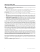
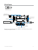
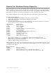
ter ter nter Wiring Diagram Valet switch Control button LED Status LED Control Center 6211T Valet switch Control button LED Status LED LIGHT FLASH POLARITY (10A (MAXIMUM) FUSE JUMPER) Control Center Bitwriter/SmartStart Port 10A FUSE MINI ATM RPN: 8540 Thermistor/Temp Sensor Sensor 1 Remote Start 10-pin Harness Sensor 2 5x04 IMPORTANT! Neutral Safety switch must be plugged in and in the ON position Neutral Safety Switch ON RF Port for IVU Main 6-pin Harness Door Lock Port Control Cente
Wiring Connections Main Harness (H1), 6-pin connector H1/1 RED (+)12VDC CONSTANT INPUT H1/2 BLACK (-) CHASSIS GROUND H1/3 BROWN (+) SIREN OUTPUT H1/4 WHITE/BROWN PARKING LIGHT ISOLATION WIRE - PIN 87a of onboard relay H1/5 WHITE PARKING LIGHT OUTPUT H1/6 ORANGE (-) 500mA GROUND WHEN ARMED OUTPUT H2 Harness, 24-pin connector PINK/WHITE 1 3 5 BLACK/WHITE 2 4 6 23 VIOLET/WHITE INSERTION SIDE 24 GREEN/WHITE H2/1 PINK/WHITE (-) 200mA IGNITION/FLEX RELAY CONTROL OUTPUT H2/2 BLACK/WHIT
Remote Start, (H3) 10-pin connector H3/1 PINK (+) IGNITION 1 INPUT/OUTPUT H3/2 RED/WHITE (87) FLEX RELAY +12V INPUT (30A FUSED) H3/3 ORANGE (+) ACCESSORY OUTPUT H3/4 VIOLET (+) STARTER OUTPUT (CAR SIDE OF THE STARTER KILL) H3/5 GREEN (+) STARTER INPUT (KEY SIDE OF THE STARTER KILL) H3/6 RED IGNITION 1 +12V INPUT (30A FUSED) H3/7 PINK/WHITE (30) FLEX RELAY OUTPUT (car side of ign, acc or starter wire) H3/8 PINK/BLACK (87a) FLEX RELAY INPUT (key side of ign, acc or starter wire if neede
Virtual Tach handles disengaging the starter motor during remote starting – it does not address over-rev. If the customer wants to have the over-rev protection capability, the tach wire must be connected. Important: After successfully learning Virtual Tach, a small minority of vehicle starters may over crank or under crank during remote start. The Bitwriter can be used fine tune the starter output time in 50mS increments to compensate for such an occurrence.
Remote Start Shutdown/Startup Diagnostics Shutdown diagnostics: If the remote start activates but fails to stay running, the remote start module has the ability to inform you of what may have caused the remote start failure. Before performing shutdown diagnostics it is important that you let the remote start shut off on its own i.e. let it attempt to start 3 times then shut down, if this is not done the unit will report the shutdown you used to shut off the remote start.
Remote Pairing Prepare the vehicle system to be Paired with a new remote 1. Open a door. 2. Turn the key to the ON position. 3. Within 5 seconds press and release the Control button on the Control Center one time. 4. Within 5 seconds, press and hold the Control button on the Control Center. The status LED will flash one time and the siren then chirps to confirm the vehicle is ready for remote pairing. 5. Release the Control button and proceed below.
Programming System Features The System Features Learn Routine dictates how the unit operates. It is possible to access and change most of the feature settings using the Control button. 1. Open a door. 2. Turn the ignition on, then off. 3. Select a Menu. Press and hold the Control button. The number of siren chirps indicates the menu number. 1 chirp indicates menu 1, 2 chirps - menu 2 and 3 chirps for menu 3. 4. When the desired menu chirps are heard, release the Control button. 5. Select a Feature.
Feature Menus Default settings are Opt. 1 (in bolder type). New features are bold with grey background. Menu 1 - Security Menu Item Feature Opt. 1 Opt. 2 Opt. 3 Opt.4 Opt. 5+ 1 System Arming Mode Active Passive Arm w/o lock Passive Arm w/lock Auto re-arm w/o lock Auto re-arm w/ lock 2 Panic Mode On Ign Off only Off 3 Confirmation Chirps On w/Warn chirps On On w/Warn chirps Off Off w/ Warn chirps On Off w/ warn chirps Off 4 Siren Duration 30 sec. 60 sec.
4. Siren Duration 1. 30sec: the siren output for full trigger activations and Panic mode is 30 seconds 2. 60sec: the siren output for full trigger activations and Panic mode is 60 seconds 5. Ign-controlled Locks 1. No Ign-locking: the door lock/unlock outputs will not activate when ignition is turned on/off 2. Lock & Unlock: the door lock & unlock output will activate when ignition is turned on & off 3. Lock Only: the door lock output will activate when ignition is turned on 4.
Menu 2 - Convenience Menu Item Feature Opt. 1 Opt. 2 Opt. 3 Opt.4 Opt. 5+ 1 One-time Bypass One time bypass Off One time bypass On 2 Nuisance Prevention On Off 3 Override Pulse count 1 2 3 4 5 4 Door Trigger Error Chirp On Off 5 Ign-controlled Dome light On Off 6 OEM Alarm Disarm w/AuxTrunk On Off 7 OEM Alarm Disarm Output With Unlock Before Unlock 8 OEM Alarm Disarm Pulses 1 2 9 Aux 1 Output type Validity Latch Latch/reset/ign 30 sec.
1. On: the OEM Alarm Disarm wire will pulse as programmed when the Aux/Trunk output is activated 2. Off: the OEM Alarm Disarm wire will not pulse when the Aux/Trunk output is activated 7. OEM Alarm Disarm Output (H2/4 wire) 1. With Unlock: the OEM Alarm Disarm wire will pulse as programmed at the same time as the unlock (Blue) wire 2. Before Unlock: the OEM Alarm Disarm wire will pulse as programmed before the unlock wire 3.
Menu 3 - Remote start Menu Item Feature Opt. 1 Opt. 2 Opt. 3 Opt.4 1 Transmission Mode Manual Automatic 2 Engine Checking Mode Virtual Tach 3 Cranking Time 0.6 sec. Voltage Off Tachometer 0.8 sec. 1.0 sec. 1.2 sec. 1.4 (5)/ 1.6 (6)/ 1.8 (7) 2.0 (8)/ 4.0 (9) 60 min. On- 10 min. 4 Remote Start Runtime 12 min. 24 min. 5 Activation Pulse Count 1 2 6 Turbo Mode No Turbo Mode On-1 min. On-3 min. On-5 min. 7 Timer Mode Runtime 12 min. 3 min. 6 min. 9 min.
6. Turbo Mode 1. No turbo Mode: Turbo mode is not available 2. On – 1/3/5/10 minutes: Turbo Mode is available and, when activated, the engine will run for the duration set per the selected option 7. Timer Mode Runtime • 12/3/6/9 minutes: sets the runtime when the engine is started by the Timer Mode and SmartStart features 8. Flex 1. 2. 3.
locked) during remote start and after shut down 2. On: the Door lock and Factory Alarm Re-arm outputs will arm/lock the vehicle during remote start and after shutdown Bitwriter - Only Options If programming with the Bitwriter®, the learn routine can be locked or unlocked. If the learn routine has previously been locked, it must be unlocked with Bitwriter® - this cannot be done manually with the Control button. The Bitwriter® gives you access to a wider range of system options.
1. Zone 4 Sensor Type: sets the Zone 4 (Sensor 2) name to be displayed in the Text Field for Warn-away and Full Trigger activations 2. Siren Duration: sets the Full Trigger output duration in 1 second intervals up to 180 seconds. 3. Aux/Trunk Icon Type: sets the Accessory animation to be displayed on the screen when the Aux/Trunk output is activated/de-activated 4. Aux 1 Timed Output: sets the output duration in 1 second intervals up to 90 seconds for Aux 1 5.
Basic Remote Functions See Owner’s guide for functionality details on both the LE and 1-way companion remote control. Reset and Deletion If a feature/virtual tach needs to be reset or the remote controls need to be deleted, use the following procedure. 1. Open a door. (The green wire, H2/6, or the violet, H2/12 must be connected.) 2. Turn the ignition to the ON position (The heavy gauge pink wire must be connected). 3.
Table of Zones A zone is represented by the number of status LED flashes used by the system to identify a particular type of input. Zone Description Input Description 1 Trunk Pin H2/19 Blue wire 2 Instant trigger: a heavier impact detected by the onboard shock sensor Shock sensor.
Troubleshooting: Remote Start The remote start will not activate the remote start 1. Check remote startup diagnostics. 2. Is the neutral safety switch plugged in and turned on? 3. If the vehicle has an automatic transmission, make sure the remote start is programmed for Automatic Transmission mode. 4. Is the remote programmed to the system? 5. Can the remote start be activated manually by applying a ground pulse to the H2/21 White/Blue wire? 6. Check the harnesses and their connections.
The vehicle starts, but will only run for 10 seconds 1. Is the remote start programmed for voltage sense? If this does not work, a tach wire should be used. 2. Check shutdown diagnostics. The climate control system does not work while the unit is operating the vehicle. 1. Either the wrong accessory wire is being energized or more than one ignition or accessory wire must be energized in order to operate the climate control system. 2.