Sunny Boy SB 2500 and SB 3000 String Inverter for Photovoltaic Plants Installation Guide Version 1.
SMA Technologie AG Table of Contents Table of Contents 1 Explanation of the Symbols Used . . . . . . . . . . . . 5 2 2.1 2.2 2.3 Foreword . . . . . . . . . . . Target Group . . . . . . . . . Appropriate Usage. . . . . Validity of Documentation 3 Safety Instructions . . . . . . . . . . . . . . . . . . . . . . . . 9 4 4.1 4.2 Overview . . . . . . . . . . . . . . . . . . . . . . . . . . . . . . 11 Unit Description . . . . . . . . . . . . . . . . . . . . . . . . . . 11 External Dimensions . . . . . . .
SMA Technologie AG Table of Contents 8.2 Sunny Boy SB 3000 . . . . . . . . . . . . . . . . . . . . . . . 37 8.2.1 8.2.2 PV Generator Connection Data . . . . . . . . . . . . . . . . . . . . . . . .37 Grid Connection Data . . . . . . . . . . . . . . . . . . . . . . . . . . . . . .38 8.3 General Data. . . . . . . . . . . . . . . . . . . . . . . . . . . . 39 8.3.1 8.3.2 Efficiency of the Sunny Boy SB 2500 . . . . . . . . . . . . . . . . . . . .40 Efficiency of the Sunny Boy SB 3000 . . . . . . . . . .
SMA Technologie AG Explanation of the Symbols Used 1 Explanation of the Symbols Used To ensure optimum use of this document, note the following explanation of the symbols used. This symbol indicates an example. This symbol indicates a note which, if ignored, will make the procedure or operation more difficult. This symbol indicates a fact which, if not observed, could result in damage to components or represent a danger to persons. Read these passages especially carefully.
Explanation of the Symbols Used Page 6 SB25_30-11:SE0307 SMA Technologie AG Installation Guide
SMA Technologie AG Foreword 2 Foreword The Sunny Boy is equipped with the SMA grid guard. This is a type of automatic disconnection device. This means that the Sunny Boy complies with the VDEW (Verband der Elektrizitätswirtschaft – German Electricity Industry Association) regulations for the connection and parallel operation of power-generating systems to the low-voltage grid of the energy supply company and with DIN VDE 0126-11, which forms part of these regulations.
SMA Technologie AG Foreword 2.2 Appropriate Usage Warning! The Sunny Boy is designed for operation in grid-connected PV systems. Use of the Sunny Boy for any purpose other than those specified in this documentation will lead to the loss of the right to all warranty claims and may lead to a fault in the device. This includes, among other things, the operation with voltage sources without any current limit. When in doubt, contact SMA. 2.
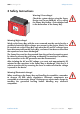
SMA Technologie AG Safety Instructions 3 Safety Instructions Warning! Overvoltage! Check the system design using the Sunny Design tool (www.SMA.de) or by calling the Sunny Boy Hotline. Overvoltages lead to the destruction of the Sunny Boy. Warning! High voltage! Work on the Sunny Boy with the cover removed must be carried out by a qualified electrician! High voltages are present in the device.
Safety Instructions Page 10 SB25_30-11:SE0307 SMA Technologie AG Installation Guide
SMA Technologie AG Overview 4 Overview 4.1 Unit Description The following diagram gives a schematic overview of the various components and connection points inside the Sunny Boy with the cover removed: Varistors, section 9 Communication socket Communication socket (RS232, RS485, NLM Piggy-Back, radio), section 11 Sunny Display Operating status LEDs Jumper slot for communication Plug socket (AC), section 6.2.
SMA Technologie AG Overview 4.
SMA Technologie AG Installation Requirements 5 Installation Requirements Check that all of the requirements listed below are met before installing and commissioning the Sunny Boy. 5.1 Installation Location Requirements The Sunny Boy SB 2500 weighs 30 kg, the Sunny Boy SB 3000 weighs 32 kg. Take this weight into account when choosing the installation location and method of installation. The ambient temperature must not be outside the -25 °C to +60 °C range.
SMA Technologie AG Installation Requirements When choosing the installation location, be sure to observe the following: Warning, high voltage! Unintentionally pulling out the DC plug connectors under load can damage the plugs and could result in personal injury! Install the Sunny Boy in such a way that it is not possible (e.g. for children) to unplug the DC plug connector unintentionally.
SMA Technologie AG Installation Requirements 5.2 PV Generator Requirements The Sunny Boy is designed to be connected to up to three strings (PV modules wired in series) having a homogenous structure (modules of the same type, identical orientation and tilt). Sunny Design will assist you in the system design and checking of the string size for a given type of inverter. Further information on Sunny Design is available at www.SMA.de.
SMA Technologie AG Installation Requirements Rating for a Line Circuit Breaker in a Photovoltaic Power Generating System Operated in Parallel to the Low Voltage Grid Various factors should be taken into account when selecting line circuit breakers.
SMA Technologie AG Installation Requirements For optimum operation of the inverters, the grid impedance of the AC cable must not exceed 1 Ohm. This is necessary, amongst other things, for the correct operation of the impedance monitoring. In addition, we recommend dimensioning the cable crosssection so that output losses do not exceed 1 % at nominal power. Output losses as a function of cable length and cross-section are shown in the graphs below.
SMA Technologie AG Installation Requirements Output Losses of the Sunny Boy SB 3000 Output losses Do not use cables where losses will exceed 1.0 % Cable length Cable cross-section 1.5 mm² 2.5 mm² Max. length 7.5 m 12.
SMA Technologie AG Installation Requirements The Sunny Boy is designed for operation on 220 - 240 V grids at a grid frequency of 50 / 60 Hz. When connecting an inverter to the public grid, follow the connection requirements of the local grid operator. Limit values for AC output Voltage range (complying with DIN VDE 198 V ... 253 / 260 V a 0126-1-1) Frequency range (complying with DIN 47.55 Hz ... 50.2 Hz VDE 0126-1-1) Voltage range) range (extended operating 180 V ...
Installation Requirements Page 20 SB25_30-11:SE0307 SMA Technologie AG Installation Guide
SMA Technologie AG Installation 6 Installation 6.1 Mounting the Device To make the job easier, we recommend you use the supplied wall bracket to mount the Sunny Boy. For vertical installation and installation on solid concrete or block walls, for example, you can fit the bracket using 6 mm x 50 mm hexagon bolts to DIN 571 standard, stainless steel type, and with wall anchors type SX 8.
SMA Technologie AG Installation 1. Mount the wall bracket (1). To mark the positions to drill the holes, you can use the wall bracket as a drilling template. 2. Now hang the Sunny Boy onto the wall bracket (2) using its upper mounting plate so that it cannot be moved sideways. 3. Secure the Sunny Boy in position by screwing the supplied M6x10 bolt into the central threaded hole at the bottom of the bracket (3). 4. Make sure that the Sunny Boy is positioned securely on the bracket. 6.
SMA Technologie AG Installation View from below Opening for the optional Electronic Solar Switch Plug and socket connector for connection of the solar modules Installation Guide AC plug for the grid connection Opening for optional communication via RS232, RS485 or radio (PG16) SB25_30-11:SE0307 Page 23
SMA Technologie AG Installation 6.2.1 Connecting the AC Output Warning! Voltage! Before you connect the mains cable to the AC connection socket, make sure that no voltage is present at the cable. A round plug connector system is used, which allows various cable diameters to be used in the cable outlet. For this reason, the accessories kit includes a PG13.5 pressure screw and a PG16 pressure screw. Check which screw fitting is the right one for your AC cable.
SMA Technologie AG 5. Installation Now take the AC connection socket parts from the accessories kit and connect up the cable, with shielding and insulation stripped, as described on the following pages. Cord grip for PG13.5 Sealing ring for PG13.5 Pressure screw for PG13.
SMA Technologie AG Installation Connecting the AC Output with PG13.5 To connect a cable with a maximum cross-section of 13.5 mm², proceed as follows. 1. 2. Press the sealing ring (1) into the cord grip (2). (1) (2) Now slide the pressure screw (3) over the cable first of all, followed by the cord grip with the sealing ring (4) in it. Now slide the threaded sleeve (5) over the cable. (3) (4) (5) 3. 4. Now connect the individual conductors to the socket element in sequence.
SMA Technologie AG 5. Now screw the threaded sleeve (7) onto the socket element (8) and tighten it. (8) 6. Installation (7) Now screw the pressure screw (9) into the threaded sleeve (10) and tighten it. The cord grip with the sealing ring is pressed into the threaded sleeve and can no longer be seen. (10) (9) The AC connection socket is now fully assembled. If you are not going to connect up the Sunny Boy immediately, close the socket element using the cap supplied in the accessories kit.
SMA Technologie AG Installation Connecting the AC Output with PG16 To connect a cable with a cross-section between 13.5 mm² and 16 mm², proceed as follows. 1. First of all, slide the pressure screw with the PG16 screw fitting (1) onto the cable. Now slide the threaded sleeve (2) over the cable. (1) (2) 2. 3. Now connect the individual conductors to the socket element in sequence. - Protective earth PE (green/yellow) to the screw terminal with the earth sign.
SMA Technologie AG 5. Now screw the pressure screw (6) into the threaded sleeve (7) and tighten it. 6. Firmly tighten the screw fitting against the seal and strain relief. Installation (7) (6) The AC connection socket is now fully assembled. If you are not going to connect up the Sunny Boy immediately, close the socket element using the cap supplied in the accessories kit.
SMA Technologie AG Installation 6.2.2 PV String (DC) Connection To connect up the input, follow these steps: 1. Make sure the PV generator connectors have the right polarity and do not exceed the maximum string voltage of 600 V (DC). See also section 5.2 "PV Generator Requirements" (Page 15). Warning! Dangerously high voltages may be present. Danger of death! 2. Taking one DC plug connector at a time, measure the direct current voltage between one DC plug connector of a string and ground potential. 3.
SMA Technologie AG Installation 6.3 Commissioning You can commission the Sunny Boy when: • the housing cover is securely screwed shut, • the AC (grid) cable is connected correctly, • the DC cables (PV strings) are fully connected and the unused DC plug connectors on the bottom of the housing are closed using the protective caps. How to Commission the Inverter 1. First of all, switch the line circuit breaker to the "on" position. 2.
SMA Technologie AG Installation Green Red Yellow Status shines continuously is not shining is not shining OK (working mode) shines continuously is not shining failure shines continuously OK (initialization) is not shining is not shining OK (stop) shines continuously is not shining failure is not shining is not shining OK (waiting, grid monitoring) shines continuously is not shining failure is not shining is not shining OK (derating) shines continuously is not shining failure
SMA Technologie AG Opening and Closing the Sunny Boy 7 Opening and Closing the Sunny Boy Warning! If you need to open the device for whatever reason, pay attention to section 3 "Safety Instructions" (Page 9). 7.1 Opening the Sunny Boy Warning! Follow the sequence below under all circumstances! 1. Switch the line circuit breaker to the "off" position. 2. Disconnect the PV generator from the Sunny Boy. 3. Wait 30 minutes! 4.
Opening and Closing the Sunny Boy Page 34 SB25_30-11:SE0307 SMA Technologie AG Installation Guide
SMA Technologie AG Technical Data 8 Technical Data 8.1 Sunny Boy SB 2500 8.1.1 PV Generator Connection Data Description Abbr. Setting Max. input open circuit voltage UPV 0 600 V (based on -10 °C cell temperature) Input voltage, MPP range UPV 224 V ... 600 V Max. input current IPV, max 12 A Max.
SMA Technologie AG Technical Data 8.1.2 Grid Connection Data Description Abbr. Setting Nominal output power PACnom 2300 W Peak output power PAC, max 2500 W Nominal output current IACnom 10 A Harmonic distortion of output KIAC current (at KUgrid < 2 %, PAC > 0.5 PACnom) <4% Short-circuit proofing grid-side via current regulation Operating range, grid voltage UAC 180 ... 265 V AC Germany: 198 ...
SMA Technologie AG Technical Data 8.2 Sunny Boy SB 3000 8.2.1 PV Generator Connection Data Description Abbr. Setting Max. input open circuit voltage UPV 0 600 V (based on -10 °C cell temperature) Input voltage, MPP range UPV 268 V ... 600 V Max. input current IPV, max 12 A Max.
SMA Technologie AG Technical Data 8.2.2 Grid Connection Data Description Abbr. Setting Nominal output power PACnom 2750 W Peak output power PAC, max 3000 W Nominal output current IACnom 12 A Harmonic distortion of output KIAC current (at KUgrid < 2 %, PAC > 0.5 PACnom) <4% Short-circuit proofing grid-side via current regulation Operating range, grid voltage UAC 180 ... 265 V AC Germany: 198 ...
SMA Technologie AG Technical Data 8.3 General Data For a detailed description of the device, see the operating manual. General data Protection degree (DIN EN 60529) IP65 Dimensions (w x h x d) 434 mm x 295 mm x 214 mm (approx.) Weight Sunny Boy SB 2500: approx. 30 kg Sunny Boy SB 3000: approx.
SMA Technologie AG Technical Data 8.3.1 Efficiency of the Sunny Boy SB 2500 Efficiency Max. efficiency ηmax 94.1 % European standard efficiency ηeuro 93.2 % Efficiency [%] The efficiency of the Sunny Boy SB 2500 depends mainly on the input voltage of the connected PV strings. The lower the input voltage, the higher the efficiency.
SMA Technologie AG Technical Data 8.3.2 Efficiency of the Sunny Boy SB 3000 Efficiency Max. efficiency ηmax 95 % European standard efficiency ηeuro 93,6 % Efficiency [%] The efficiency of the Sunny Boy SB 3000 depends mainly on the input voltage of the connected PV strings. The lower the input voltage, the higher the efficiency.
SMA Technologie AG Technical Data 8.4 Operating Parameters 8.4.1 Explanation of the Operating Parameters Name Explanation ACVtgRPro Voltage rise protection (only relevant for Germany). Sunny Boys can feed into the public grid in Germany with up to 260 V AC. However, DIN VDE 0126-1-1 stipulates that the average AC voltage over 10 minutes must not exceed 253 V. If the average over 10 minutes exceeds the threshold value of 253 V, the inverter disconnects itself from the grid.
SMA Technologie AG Technical Data Name Explanation dFac-Max Maximum "grid frequency change" before the grid monitoring system disconnects the device from the grid. dZac Maximum "grid impedance change" before the grid monitoring system disconnects the device from the grid. E_Total Total energy yield for the inverter. This change may be necessary when you replace the Sunny Boy and want to use the data stored in the old device.
SMA Technologie AG Technical Data Name Explanation Upv-Start The DC voltage required before the inverter begins feeding power into the grid. This value is above the minimum MPP voltage which is required in order to always guarantee safe connection to the grid, and to minimize grid relay wear. If, after disconnection from the grid, and in the absence of any further faults, the inverter does not automatically reconnect to the grid, this parameter can be decreased in small steps.
SMA Technologie AG Technical Data 8.4.2 Parameter Settings for Germany Warning! Unauthorized changes to the operating parameters may result in: • injury or accidents as a result of changing the internal safety routines in the Sunny Boy, • voiding the Sunny Boy's operating approval certificate, • voiding the Sunny Boy's warranty. Never change the parameters of your Sunny Boy without express authorization and instructions. The grayed-out parameters are only displayed in installer mode.
SMA Technologie AG Technical Data Name Short descr. Speicherfunkt. Value range Factory setting Sunny Boy SB 2500 Sunny Boy SB 3000 Default Parameter, Reset Betriebsdaten, Reset Fehler no no T-Start * s 5 ... 300 10 10 T-Stop s 1 ... 1800 2 2 Uac-Max * V 180 ... 300 260 260 Uac-Min * V 180 ... 300 198 198 Upv-Start V 250 ... 600/ 290 ... 600 300 330 Usoll-Konst V 250 ... 600 600 600 Parameters designated with * are safety-related grid monitoring parameters.
SMA Technologie AG Technical Data 8.4.3 Country-specific Parameter Settings The parameters listed below represent country-specific settings and are only displayed in installer mode. All other parameters are international and can be viewed in the table in section 8.4.2 "Parameter Settings for Germany" (Page 45). Sunny Boy SB 2500 Name Short descr. Country settings Germany Default Great Britain Spain GER/VDE0126-1-1 GB/G83 SP/RD1663 dFac-Max Hz/s 4 0.
SMA Technologie AG Technical Data 8.4.4 Fixed Parameters The following parameters are displayed in the parameter list but cannot be changed: Name Short descr.
SMA Technologie AG Technical Data 8.5 Certificate 8.5.1 CE Declaration of Conformity CE Declaration of Conformity for utility interactive inverters Product: Type: Sunny Boy SB 700, SB 1100, SB 1100LV, SB 1700, SB 2100TL, SB 2500, SB 2800i, SB 3000, SB 3300TL, SB 3300TL HC We declare that the above specified devices are compliant with the regulations of the European Community, in terms of the design and the version fabricated by SMA.
Technical Data SMA Technologie AG 8.5.2 SMA Grid Guard Certificate The Sunny Boy is equipped with the automatic disconnection device “SMA grid guard” which has been awarded a certificate of confidence by the Professional Association for Electric Technology and Precision Mechanics..
SMA Technologie AG Replacing the Varistors 9 Replacing the Varistors The Sunny Boy is a complex high-technology device. As a result, the possibilities for fixing faults on site are limited to just a few items. Do not attempt to carry out repairs other than those described here. Use the SMA Technologie AG 24-hour replacement service and repair service instead.
Replacing the Varistors 6. SMA Technologie AG If the measured voltages are constant and their total is roughly the same as the open circuit voltage of the string, then there is a ground fault in this string. Its approximate location can be deduced from the relationships between the voltages. Repeat points 3 and 4 for each string. If you found a ground fault, it is probably not necessary to replace the varistors. Instead, make sure the ground fault is fixed.
SMA Technologie AG 9. Replace the varistor in question with a new one as shown in the illustration to the right. Ensure the varistor is installed the right way around! If you do not receive a special tool for operating the terminal clamps together with your replacement varistors, contact SMA. As an alternative, the terminal contacts can be operated using a suitable screwdriver.
Replacing the Varistors SMA Technologie AG 14. Now check whether the LED display on the Sunny Boy indicates that the device is functioning correctly. If no ground fault and no defective varistor were found, there is probably a fault in the Sunny Boy. In this case, contact the SMA Hotline to discuss what to do next.
SMA Technologie AG Rating for a Line Circuit Breaker 10 Rating for a Line Circuit Breaker Example for the thermal rating for a line circuit breaker in a photovoltaic powergenerating system operated in parallel with the low voltage grid. We assume a PV system with 9 Sunny Boy inverters, with three inverters per phase.
Rating for a Line Circuit Breaker SMA Technologie AG When selecting line circuit breakers, a number of load factors need to be taken into account. These can be found in the respective data sheets. Example for the thermal selection of a 16 A line circuit breaker with B sensitivity and no gap between the circuit breakers: For example, one manufacturer's circuit breaker may be designed for an ambient temperature of 50 °C.
SMA Technologie AG Rating for a Line Circuit Breaker Summary The selected line circuit breaker cannot be used in our example case since the maximum current-carrying capacity for fault-free operation is lower than the maximum output current of the inverter used. It will trip under rated operating conditions! In this case one solution would be to ensure there is an 8 mm gap between the circuit breakers. This would mean that the reduction factor is 0.98 instead of 0.77.
Rating for a Line Circuit Breaker Page 58 SB25_30-11:SE0307 SMA Technologie AG Installation Guide
SMA Technologie AG The Communication Interface 11 The Communication Interface Warning! Installation or replacement of the communication interface is only to be carried out by a qualified electrician. The communication interface is used to communicate with SMA communication devices (e.g. Sunny Boy Control, Sunny WebBox) or a PC with appropriate software (e.g. Sunny Data Control). Depending on the selected communication interface, up to 2500 inverters can be interconnected.
The Communication Interface SMA Technologie AG 11.1 Connection of the Communication Interface Warning! When opening the Sunny Boy, follow all the safety instructions as described in section 3. Electrostatic discharges are an acute danger to the Sunny Boy and to the communication interface. Ground yourself by touching PE before removing the communication interface from the packaging, and before touching any components within the Sunny Boy.
SMA Technologie AG The Communication Interface F 23 57 D E PE 23 57 C B A A Housing feed-through in the base of the Sunny Boy B Cable route (gray surface) C PE connector D Screw terminals for connection of the communication wires E Jumper slots F Interface port 11.1.1 Jumper Functions Jumper A Jumper B Jumper C RS232 - - - RS485 termination bias 1 bias 2 NLM - - - Radio - - - A detailed description of the jumper functions can be found in the communication device manual.
The Communication Interface Page 62 SB25_30-11:SE0307 SMA Technologie AG Installation Guide
SMA Technologie AG Contact 12 Contact If you have any questions or technical problems concerning the Sunny Boy, contact our hotline. Have the following information available when you contact SMA: • Inverter type • Type and number of modules connected • Communication method • Serial number of the Sunny Boy • Blink code or display of the Sunny Boy Address: SMA Technologie AG Hannoversche Strasse 1 - 5 34266 Niestetal Germany Tel.:+49 (561) 95 22 - 499 Fax:+49 (561) 95 22 - 4699 hotline@SMA.de www.
Legal Restrictions SMA Technologie AG The information contained in this document is the property of SMA Technologie AG. Publishing its content, either partially or in full, requires the written permision of SMA Technologie AG. Any internal company copying of the document for the purposes of evaluating the product or its correct implementation is allowed and does not require permission. Exclusion of liability The general terms and conditions of delivery of SMA Technologie AG shall apply.
Sales Solar Technology www.SMA.de SMA Technologie AG Hannoversche Strasse 1–5 34266 Niestetal, Germany Tel. : +49 561 9522 4000 Fax: +49 561 9522 4040 E-Mail: Info@SMA.