PVI 1800/PVI 2500 INSTALLATION AND OPERATION MANUAL Residential/Commercial Grid-Tied Photovoltaic Inverter © 2008, Solectria Renewables Subject to Change REV A
PVI 1800/PVI 2500(Rev A) Installation and Operation Manual IMPORTANT SAFETY INSTRUCTIONS This manual contains important instructions that shall be followed during installation and maintenance of the PVI 1800/PVI 2500 Inverter. To reduce the risk of electrical shock, and to ensure the safe installation and operation of the inverter, the following safety symbols are used to indicate dangerous conditions and important safety instructions.
PVI 1800/PVI 2500(Rev A) Installation and Operation Manual IMPORTANT SAFETY INSTRUCTIONS All electrical installations shall be done in accordance with the local and national electrical codes ANSI/NFPA 70, NEC. The PVI 1800 and 2500 inverters are listed to UL1741/IEEE1547 (and comply with IEEE 62.41). The PVI 1800/PVI 2500 contains no user serviceable parts. Do not open the inverter case as this will damage the NEMA4, IP65 seal.
PVI 1800/PVI 2500(Rev A) Installation and Operation Manual Table of Contents 1 Introduction ................................................................................................................... 2 Installation ..................................................................................................................... 2.1 Checking for Shipping Damage ............................................................................ 2.2 Inverter Mounting .....................................
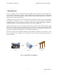
PVI 1800/PVI 2500(Rev A) Installation and Operation Manual 1 Introduction The PVI 1800/PVI 2500 is a residential/commercial single phase, grid-tied PV inverter designed to be inter-connected to the electric utility grid. With this manual the PVI 1800/PVI 2500 can be installed and operated safely. This installation guide is used as reference for the commissioning and as a guideline on how to use the inverter most effectively.
PVI 1800/PVI 2500(Rev A) Installation and Operation Manual The string PV concept The use of string PV concept significantly reduces the cabling costs on a photovoltaic system. The use of just one, two (or in some cases 3) parallel strings of PV modules in series has proven advantageous by delivering a high operating voltage to the solar inverter. This advantage is primarily reflected in a higher efficiency of the inverter.
PVI 1800/PVI 2500(Rev A) Installation and Operation Manual The heat sink serves to conduct away heat generated from energy losses in the power electronics. Internal temperature regulation provides protection against excessively high temperatures inside the PVI 1800/PVI 2500. The maximum power processed from the PV array is automatically reduced to limit excessive inverter temperature. The PVI 1800/PV2500 will only operate in parallel with the utility grid.
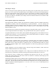
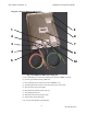
PVI 1800/PVI 2500(Rev A) Installation and Operation Manual Diagram of the PVI 1800/PVI 2500 Features 1 9 2 8 3 7 4 6 5 10 Fig.
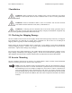
PVI 1800/PVI 2500(Rev A) Installation and Operation Manual 2 Installation WARNING: Before installing the PVI 1800/PVI 2500, read all instructions and caution markings in this manual and on the PVI 1800/PVI 2500 as well as on the photovoltaic modules. WARNING: Electrical installation shall be done in accordance with all local electrical codes and the National Electrical Code (NEC), ANSI/NFPA 70.
PVI 1800/PVI 2500(Rev A) Installation and Operation Manual Notes regarding mounting and placement of the inverter Criteria for device mounting: Because the inverter is in a NEMA4/IP65 sealed enclosure, the inverter can be mounted outdoors. The very longest life for the inverter can be achieved by mounting it in a clean, dry and cool location even given the unit’s robust construction and design for efficient cooling. It is recommended to keep the unit out of direct rain.
PVI 1800/PVI 2500(Rev A) Installation and Operation Manual The ambient temperature must be between –4o F (–20o C) and +131o F (+55o C) for full continuous, full power operation. (The inverter will automatically reduce power or shut down to protect itself if the ambient air temperature rises above 131o F (55o C).) The National Electrical Code (NEC) requires that the inverter be connected to a dedicated AC circuit and no other AC outlets or device may be connected to this circuit.
PVI 1800/PVI 2500(Rev A) Installation and Operation Manual Fig.
PVI 1800/PVI 2500(Rev A) Installation and Operation Manual Fig. 5 PVI 1800/PVI 2500 Mounting Screw Pattern Mounting Details Using the mounting diagram Fig. 5, for screw positions on, wall. Four #10 or #12 screws can be used. It is recommended to use stainless steel screws, especially if used outdoors. Be sure to verify sheer and pullout strength of anchors or other wall attachments. NOTE: Always use all 4 mounting screws. It is easiest to layout the 4 screw mounting pattern using Fig.
PVI 1800/PVI 2500(Rev A) Installation and Operation Manual NOTE: The inverter is set up with pre-wired AC and DC connections to make it very easy and quick to connect to a DC disconnect to the left of the inverter and an AC disconnect to the right. (Connections can also be made to junction boxes.) 2.3 Electrical Connection and Connection To Electrical Utility Grid Fig.
PVI 1800/PVI 2500(Rev A) Installation and Operation Manual The negative DC photovoltaic connection is grounded within the inverter through the ground fault detection and interrupt circuit (GFDI). The PV negative should not be grounded at any other point in the system. The PV positive must never be grounded at any time. AC and DC (PV) Connections: The PVI 1800 and PVI 2500 inverters are pre-wired with 54” (1.
PVI 1800/PVI 2500(Rev A) Installation and Operation Manual Multiple Units: Multiple PVI 1800 or PVI 2500 units can be used at the same location/facility assuming all codes are followed including NEC, local building codes and area utility guidelines. If multiple units are used, each inverter should have its own dedicated circuit breaker, and a PV string must only be wired to one inverter (although multiple PV strings can be used on each inverter up to unit ratings and power levels).
PVI 1800/PVI 2500(Rev A) Installation and Operation Manual Suggested AC Disconnect: 240V AC, 30A, 2 Blade, NEMA 3R Rain-proof NEMA 3R, no fuse Rain-proof NEMA 3R, fusible Rain-proof NEMA 3R, no fuse Part Number DU22IRB TG3221R TGN3321R Manufacturer Square D GE GE Pull-out disconnect, 3R, no fuse 3800 Millbank For some installations, code compliance may include indoor, NEMA 1 rated disconnects which are less expensive.
PVI 1800/PVI 2500(Rev A) Installation and Operation Manual Approximately 0.40 Ω for a 100 feet (76.2 m) 12 AWG conductors Approximately 0.24 Ω for a 100 feet (76.2 m) 10 AWG conductors Approximately 0.15 Ω for a 100 feet (76.2 m) 8 AWG conductors Conductor impedance of < 0.40 Ω is recommended The total impedance phase to phase of the grid plus the interconnecting AC conductors should be less than 1.2 Ω.
PVI 1800/PVI 2500(Rev A) Installation and Operation Manual The PV-panel open circuit voltage must be below 400V DC (Vpv < 400V DC) under all conditions as per NEC 690-7 using multiplier for cold weather OCV. Please read the Technical Info section and see PV string sizing table in Appendix C. WARNING: Even when in the off position, the DC disconnect will remain live on the PV side (“line”) when the PV modules are in daylight.
PVI 1800/PVI 2500(Rev A) Installation and Operation Manual Turning on the inverter: Turn on the dedicated 2-circuit 240/208VAC circuit breaker on the home/building electrical panel Turn on the AC disconnect Turn on the DC disconnect Watch the LED indicators for initialization (all three LEDs on) Watch for blinking green LED and high frequency switching sound (this means that the inverter is on-line and beginning to feed power into the AC circuit), the inverter is operating normally
PVI 1800/PVI 2500(Rev A) Installation and Operation Manual 4.1 Power, Ground Fault and Error LED Indicators There are three light-emitting diodes (LEDs) mounted on the front (upper right corner) to show the operating condition of the inverter. Fig. 8: Power, Ground Fault and Error Indicator The green LED "Power" shows the current operating condition. The red LED "Ground Fault" shows if a ground fault is present.
PVI 1800/PVI 2500(Rev A) Installation and Operation Manual Operating condition Description standby (night) input voltage < 120 VDC initialization unit is being initialized green: waiting, presence of valid grid conditions is yellow: checking grid being checked green: power output to grid normal daytime operation yellow: MPP or constant voltage mode LED indicator green: yellow: red: green: yellow: red: red: red: green: / yellow: / failure internal or external failure, exact descript
PVI 1800/PVI 2500(Rev A) Installation and Operation Manual 4.2 The LCD Display The PVI 1800/PVI 2500 inverter is supplied ready to operate so there are no settings, which have to be made by the user for fully automatic feeding of power into the grid. The device comes standard with a display on which various types of information can be read. Settings can be made using the entry buttons located below and information can be retrieved.
PVI 1800/PVI 2500(Rev A) Installation and Operation Manual Main menu The main menu is sub-divided into 6 menu items and each menu item contains sub-menus: - Menu N (Now) - Menu D (Day) - Menu W (Week) - Menu Y (Year) - Menu T (Total) - Menu S (Setup) Description of the menu items: Actuation of the selection buttons allows you to scroll through the main menu. The sub-menus are then selected by pressing the - button. Exit the menus by pressing the - button. ESC ENTER 1.
PVI 1800/PVI 2500(Rev A) Installation and Operation Manual Sub-menu N (Now) This menu item is used to view current values. ESC ENTER 1. Menu-N Now 1. N > AC-Power xxxx W Indication of the present power output 2. N > AC-Voltage xxxx V Indication of the present AC voltage 3. N > AC-Current xxxx A Indication of the present AC current 4. N > AC-Frequency xxxx Hz Indication of the present grid frequency 5. N > Solar Voltage xxxx V Indication of the present solar array voltage 6.
PVI 1800/PVI 2500(Rev A) Installation and Operation Manual Sub-menu D (Day) This menu item is used to call up daily values regarding power fed to the grid. ESC ENTER 2. Menu-D Day 1. D > Energy xxxx Wh Indication of the daily energy output 2. D > Revenue xxxxx.xx Dollars Indication of the daily revenue in dollars 3. D > AC-power-Max xxxx W Indication of the maximum power output during day 4. D > AC-Voltage-Max xxx V Indication of the maximum AC voltage during the day 5.
PVI 1800/PVI 2500(Rev A) Installation and Operation Manual Sub-menu W (Week) This menu item is used to call up average values for the current week. ESC ENTER 3. Menu-W Week 1. W > Energy xxxx Wh Indication of the weekly energy output 2. W > Revenue xxxxx.xx Dollars Indication of the weekly revenue in dollars 3. W > Runtime xxxx h Indication of the weekly operating time of inverter Sub-menu M (Month) This menu item is used to call up average values for the current month. ESC ENTER 4.
PVI 1800/PVI 2500(Rev A) Installation and Operation Manual Sub-menu Y (Year) This menu item is used to call up average values for the current year. ESC ENTER 5. Menu-Y Year 1. Y > Energy xxxx kWh Indication of the annual energy output 2. Y > Revenue xxxxx.xx Dollars Indication of the annual revenue in dollars 3.
PVI 1800/PVI 2500(Rev A) Installation and Operation Manual Sub-menu S (Setup), the last line of the menu. The Setup menu serves to change the default settings of the PVI 1800/PVI 2500. ESC ENTER 7. Menu-S Setup Inverter 1. S > LCD-Contrast setting 0 .. 9 Setting the brightness and contrast of the LCD display between 0 and 9 2. S > LCD-Backlight setting Auto/On/Off Setting the LCD backlight mode 3. S > Menu Mode setting Now .. Total Selection of default menu on the display 4.
PVI 1800/PVI 2500(Rev A) Installation and Operation Manual 5 Troubleshooting Diagnosis and analysing data Identifying and resolving faults The PVI 1800/PVI 2500 is fitted with a self-diagnostic system, which can recognise a majority of possible faults and show these on the display. This allows the operator to rapidly identify possible problems in the solar inverter or system. Internal communication errors Internal communication errors are indicated when a problem arises in the device.
PVI 1800/PVI 2500(Rev A) Installation and Operation Manual arises on a regular basis Check the grid voltage 205 206 207 208 Extreme grid over-voltage The inverter switches over to normal power/feed mode as soon as the power grid voltage returns to its nominal value Grid over-voltage The inverter switches over to normal power/feed mode as soon as the grid voltage returns to its nominal value Grid under-voltage The inverter switches over to normal power/feed mode as soon as the grid voltage returns
PVI 1800/PVI 2500(Rev A) Installation and Operation Manual Overview error codes Code Designation Condition The inverter resumes feeding the grid when automatic switching on of the inverter reconnects it with the grid 101 Hardware error, internal communication interrupted 203 Grid frequency too high The inverter switches to normal power/feed mode as soon as the grid frequency returns to its nominal value 204 Grid frequency too low The inverter switches to normal power/feed mode as soon as the gri
PVI 1800/PVI 2500(Rev A) Installation and Operation Manual 6 Product Warranty & RMA Policy 6.1 Warranty Policy The Solectria Renewables Warranty Policy is stated below. Solectria Renewables Warranty Coverage: Solectria Renewables Limited Warranties are provided by Solectria Renewables, LLC. ("Solectria Renewables") and cover defects in workmanship and materials.
PVI 1800/PVI 2500(Rev A) Installation and Operation Manual In the event an extended warranty option has been purchased, this extended warranty only applies to exposed outdoor locations (defined as rooftop or open/unprotected locations) if the product has been purchased to include the gasket-sealed AC and DC disconnect option or has a protective cover around 3 sides of inverter unit (back and sides) and over the top, 4”-60” away from back and top and 30”-96” from sides.
PVI 1800/PVI 2500(Rev A) Installation and Operation Manual DISCLAIMER SOLECTRIA RENEWABLES LIMITED WARRANTIES ARE THE SOLE AND EXCLUSIVE WARRANTY PROVIDED BY SOLECTRIA RENEWABLES IN CONNECTION WITH YOUR SOLECTRIA RENEWABLES PRODUCT AND ARE, WHERE PERMITTED BY LAW, IN LIEU OF ALL OTHER WARRANTIES, CONDITIONS, GUARANTEES, REPRESENTATIONS, OBLIGATIONS AND LIABILITIES, EXPRESS OR IMPLIED, STATUTORY OR OTHERWISE IN CONNECTION WITH THE PRODUCT, HOWEVER ARISING (WHETHER BY CONTRACT, TORT, NEGLIGENCE, PRINCIPLES
PVI 1800/PVI 2500(Rev A) Installation and Operation Manual WARNING: LIMITATIONS ON USE Please refer to your product user manual for limitations on uses of the product. Specifically, please note that Solectria Renewables products are not intended for use in connection with life support systems and Solectria Renewables makes no warranty or representation in connection with any use of the product for such purposes.
PVI 1800/PVI 2500(Rev A) Installation and Operation Manual 7 Technical Data Technical Information and specifications – see PVI 1800/PVI 2500 brochure for various other information and data in addition to the information in this section of the manual. (see Appendix B for info).
PVI 1800/PVI 2500(Rev A) Installation and Operation Manual Input DC (PV) specifications for PVI 1800/PVI 2500 inverter PVI 1800 PVI 2500 Input voltage MPP range 125V-350V DC 125V-350V DC Maximum open circuit voltage (under all conditions) 400V DC 400V DC Nominal Input Current 7.3A DC 10.
PVI 1800/PVI 2500(Rev A) Installation and Operation Manual Output (AC) specifications for PVI 1800/PVI 2500 Inverter: PVI 1800 PVI 2500 Continuous AC output power 1800 Watts AC 2500 Watts AC Operating voltage range +/- 10% 240/208V AC 240/208V AC Operating frequency range 59.3 to 60.5 Hz 59.3 to 60.5 Hz Maximum Continuous Output Current 7.5A @ 240V AC 8.65A @ 208V AC 10.
PVI 1800/PVI 2500(Rev A) Installation and Operation Manual 3000 2500 AC Output Power (W) Output Power 2500 Output Power 1800 2000 1500 1000 “strike” voltage 500 0 125 175 225 275 325 375 DC Input Voltage (VDC) Fig. 11 AC Output power of PVI 1800/PVI 2500 DC input current versus DC input voltage Input current DC 1800W Input current DC 2500W 16 DC Input Current (A) 14 12 10 8 6 4 2 0 125 150 175 200 225 250 275 300 325 350 375 400 DC Input Voltage (VDC) Fig.
Efficiency % PVI 1800/PVI 2500(Rev A) Installation and Operation Manual 100 95 90 85 80 75 70 0 300 600 900 1200 1500 1800 Power (Watts) Efficiency % Fig. 13a PVI 1800 efficiency plot 100 95 90 85 80 75 70 0 500 1000 1500 2000 2500 Power (Watts) Fig.
PVI 1800/PVI 2500(Rev A) Installation and Operation Manual Appendices Appendix A: Terminal assignment RS-485 / RS-232: 8 1 Top view Pin 1 2 3 4 5 6 7 8 Not used RXD (RS232) TXD (RS232) GND (RS232/RS485) TERM (RS485) RX_B (RS485) TX_A (RS485) Not used Hint! Both RJ45 connectors have the same pin-out. Use RJ45 crimping tool such as AMP/Tyco Electronics P/N 2-231652-0 Other versions of RJ45 crimping tools are also available at stores such as Radio Shack.
PVI 1800/PVI 2500(Rev A) Installation and Operation Manual Appendix B PVI 1800/PVI 2500 brochure The brochure can also be viewed on the website: www.solren.com Link: http://www.solren.com/downloads/PVI 1800_2500.pdf Appendix C Example string sizing PVI 1800/PVI 2500 (Note that the chart below is only to show how string sizing charts look. Please refer to the website version for complete and updated charts for use in all temperature zones across the country.
PVI 1800/PVI 2500(Rev A) Installation and Operation Manual Appendix D - Contact Information Solectria Renewables LLC 360 Merrimack Street Building 9 Lawrence, Massachusetts, 01843 USA Tel: 978.683-9700 Fax: 978.683-9702 Email: inverters@solren.com Website: www.solren.com Authorized Dealers and Installers – see website: www.solren.com Specific link: www.solren.com/distributors.
PVI 1800/PVI 2500(Rev A) Installation and Operation Manual Appendix D – Certification to UL 1741 / IEEE 1547 / IEEE C62.
PVI 1800/PVI 2500(Rev A) Installation and Operation Manual 46 DOCR-070570-A