
Technical data

PVI 1800/PVI 2500(Rev A) Installation and Operation Manual
42
DOCR-070570-A
Appendices
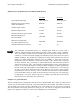
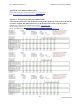
Appendix A: Terminal assignment RS-485 / RS-232:
Pin
1 Not used
2RXD (RS232)
3 TXD (RS232)
4 GND (RS232/RS485)
5 TERM (RS485)
6 RX_B (RS485)
7TX_A (RS485)
8 Not used
8 1
Top view
Hint! Both RJ45 connectors have the same pin-out.
Use RJ45 crimping tool such as AMP/Tyco Electronics P/N 2-231652-0
Other versions of RJ45 crimping tools are also available at stores such as Radio Shack.
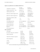
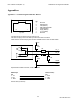
+5V
0R
Not
used
Not
used
0R
TX_A
RX_B
TERM
GND
Representative RS485 schematic, inside the inverter
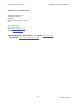
Pin
3 - TD
2 - RD
5 - GND
RS232 9
p
ol.
Pin
2 - RXD
3 - TXD
4 - GND
RJ45
(
inverter
)
RS 232 cable (schematic)
121R