
Technical data

PVI 1800/PVI 2500(Rev A) Installation and Operation Manual
8
DOCR-070570-A
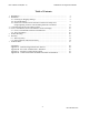
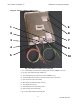
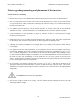
Diagram of the PVI 1800/PVI 2500 Features
Fig. 2 PVI 1800/PVI 2500 Features Diagram
(1) AC conduit fitting and conductors to building/grid (10 AWG, XHHW-2 wire) PV
(2) PV array ground fault interrupt (GFDI) fuse
(3) DC conduit fitting and conductors (10 AWG, XHHW-2 wire)
(4) Grounding Electrode Conductor connection point (on side of heat sink)
(5) Fan Connection (used on PVI 2500)
(6) RS-232/485 communication ports and caps
(7) LCD display and key pad
(8) LED indicators for basic operating status
(9) Fan assembly (on PVI 2500 only)
(10) Inverter Serial Number on bottom plate
9
8
7
6
1
2
4
5
3
10