PV Inverter SUNNY BOY 2500/3000 Installation Manual SB25_30-IA-IEN115050 | IMEN-SB25_30 | Version 5.
SMA Solar Technology AG Table of Contents Table of Contents 1 1.1 1.2 1.3 1.4 Information on this Manual. . . . . . . . . . . . . . . . . . . . . . . . . Validity . . . . . . . . . . . . . . . . . . . . . . . . . . . . . . . . . . . . . . . . . . . . Target Group . . . . . . . . . . . . . . . . . . . . . . . . . . . . . . . . . . . . . . . Additional Information . . . . . . . . . . . . . . . . . . . . . . . . . . . . . . . . Symbols Used . . . . . . . . . . . . . . . . . . . . . . . . . . . . . . . . . .
Table of Contents SMA Solar Technology AG 5.3 5.4 Setting the Display Language . . . . . . . . . . . . . . . . . . . . . . . . . . 28 PV Array Connection (DC) . . . . . . . . . . . . . . . . . . . . . . . . . . . . 29 5.4.1 Conditions for the DC Connection . . . . . . . . . . . . . . . . . . . . . . . . . . . . . . . . 29 5.4.2 Assembling the DC Connectors. . . . . . . . . . . . . . . . . . . . . . . . . . . . . . . . . . . 30 5.4.3 Opening the DC Connector . . . . . . . . . . . . . . . . . . . . .
SMA Solar Technology AG Table of Contents 9.3 Red LED is Permanently Lit . . . . . . . . . . . . . . . . . . . . . . . . . . . . 56 9.3.1 Checking the PV Array for Earth Faults . . . . . . . . . . . . . . . . . . . . . . . . . . . . . 57 9.3.2 Checking the Function of the Varistors . . . . . . . . . . . . . . . . . . . . . . . . . . . . . 59 10 10.1 10.2 10.3 10.4 Decommissioning . . . . . . . . . . . . . . . . . . . . . . . . . . . . . . . . 61 Unmounting the Inverter . . . . . . . . . . . . . . .
Table of Contents 6 SB25_30-IA-IEN115050 SMA Solar Technology AG Installation Manual
SMA Solar Technology AG Information on this Manual 1 Information on this Manual 1.1 Validity This manual describes the mounting, installation, commissioning, maintenance, and troubleshooting procedures for the following SMA inverters: • Sunny Boy 2500 (SB 2500, SB 2500-IT) • Sunny Boy 3000 (SB 3000, SB 3000-IT) Keep this manual in a convenient place for future reference. 1.2 Target Group This manual is for electrically qualified persons.
Information on this Manual SMA Solar Technology AG 1.4 Symbols Used The following types of safety precautions and general information are used in this manual: DANGER! G DANGER indicates a hazardous situation which, if not avoided, will result in death or serious injury. WARNING! WARNING indicates a hazardous situation which, if not avoided, could result in death or serious injury. CAUTION! CAUTION indicates a hazardous situation which, if not avoided, could result in minor or moderate injury.
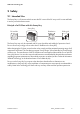
SMA Solar Technology AG Safety 2 Safety 2.1 Intended Use The Sunny Boy is a PV inverter which converts the DC current of the PV array to AC current and feeds it into the power distribution mains. Principle of a PV Plant with this Sunny Boy Sunny Boy PV modules Distribution Public grid The Sunny Boy may only be operated with PV arrays (modules and cabling) of protection class II. Do not connect any energy sources other than PV modules to the Sunny Boy.
SMA Solar Technology AG Safety 2.2 Safety Precautions DANGER! Danger to life due to high voltages in the inverter • All work on the inverter may only be carried out by an electrically qualified person. CAUTION! Risk of burns due to hot enclosure parts • Do not touch the enclosure during operation. • Only touch the lid during operation.
SMA Solar Technology AG Safety PV array earthing Comply with local regulations when earthing the modules and the PV array. SMA Solar Technology AG recommends connecting the array frame and other electrically conductive surfaces so that there is continuous conduction and to earth them in order to ensure maximum protection for installations and persons.
SMA Solar Technology AG Safety 2.3 Explanation of Symbols This section gives an explanation of all the symbols found on the inverter and on the type label. 2.3.1 Symbols on the Inverter Symbol Explanation Operation display Indicates the operating state of the inverter. Ground fault or varistor defective Read Section 9.3 "Red LED is Permanently Lit" (page 56). Error or fault Read Section 9 "Troubleshooting" (page 52).
SMA Solar Technology AG Safety 2.3.2 Symbols on the Type Label Symbol Explanation Beware of hazardous voltage. The inverter operates at high voltages. All work on the inverter may only be carried out by an electrically qualified person. Beware of hot surface. The inverter can become hot during operation. Avoid contact during operation. Observe all documentation that accompanies the inverter. The inverter must not be disposed of together with the household waste.
SMA Solar Technology AG Unpacking 3 Unpacking 3.1 Scope of Delivery Check the delivery for completeness and for any visible external damage. Contact your specialty retailer if anything is damaged or missing.
SMA Solar Technology AG Unpacking 3.2 Identifying the Inverter You can identify the inverter using the type label. The type label is on the right-hand side of the enclosure. The serial number (Serial No.) and the type (Type/Model) of the inverter, as well as device-specific characteristics are specified on the type label.
SMA Solar Technology AG Mounting 4 Mounting 4.1 Safety DANGER! Danger to life due to fire or explosion Despite careful construction, electrical devices can cause fires. • Do not mount the inverter on flammable construction materials. • Do not mount the inverter in areas where highly flammable materials are stored. • Do not mount the inverter in a potentially explosive atmosphere.
SMA Solar Technology AG Mounting • The connection area must point downward. • Never mount the device with a forward tilt. • Never mount the device with a sideways tilt. • Do not mount horizontally. • Install at eye level in order to allow operating states to be read at all times. • To ensure optimal operation, the ambient temperature should be below 40°C. • Do not expose the inverter to direct solar irradiation as this can cause excessive heating and thus power reduction.
SMA Solar Technology AG Mounting 4.3 Mounting the Inverter with the Wall Mounting Bracket CAUTION! Risk of injury due to the heavy weight of the inverter • Take the inverter's weight of approx. 32 kg into account for mounting. • Use mounting material suitable for the surface when attaching the wall mounting bracket. 1. Use the wall mounting bracket as a drilling template and mark the positions of the drill holes. 2. Attach the wall mounting bracket to the wall using appropriate screws and washers.
SMA Solar Technology AG Mounting 3. Mount the inverter with its upper anchorage bracket on the wall mounting bracket in such a way that it cannot slide out of the bracket sideways. 4. If a second protective conductor is required in the country of installation, earth the inverter and fix it securely as described in Section 5.2.3 "Connecting Additional Earthing" (page 27). 5. If a second protective conductor is not required, fix the inverter securely using the enclosed M6x12 screw. 6.
SMA Solar Technology AG Electrical Connection 5 Electrical Connection NOTICE! Electrostatic discharges can damage the inverter. Internal component parts of the inverter can be irreparably damaged by static electric discharge. • Earth yourself before touching a component part. 5.1 Overview of the Connection Area 5.1.1 Exterior View The following figure shows the assignment of the individual connection areas on the bottom of the inverter.
SMA Solar Technology AG Electrical Connection 5.1.2 Interior View The following figure shows the various components and connection areas of the open inverter. Object A B C D E F G Description Varistors Connection area and slots for optional communication via RS485 Display Operating status LEDs Jack for AC connection DC connector* Jack for the Electronic Solar Switch (ESS)** * If you have ordered the inverter without ESS, the inverter is equipped with 1 negative and 1 positive DC connector.
SMA Solar Technology AG Electrical Connection 5.2 Connection to the Power Distribution Mains (AC) 5.2.1 Conditions for the AC Connection Connection requirements of the network operator Comply with the connection requirements of your network operator. Cable dimensioning Use Sunny Design version 2.0 or higher for dimensioning the conductor cross-sectional areas (see Sunny Design programme at www.SMA.de/en).
SMA Solar Technology AG Electrical Connection Load Disconnection Unit You must install a separate miniature circuit-breaker for each inverter in order to ensure that the inverter can be securely disconnected under load. The maximum permissible fuse protection can be found in Section 11 "Technical Data" (page 63).
SMA Solar Technology AG Electrical Connection 5.2.2 Connecting the Inverter to the Power Distribution Mains (AC) Overview of the AC connection socket Object A B C D E F Description Jack element Threaded sleeve PG13.5 sealing ring PG13.5 fastening case PG13.5 pressure screw (for a cable diameter between 9 mm … 13.5 mm) PG16 cable gland (for a cable diameter between 13.5 mm ... 17 mm) Procedure 1. Choose an appropriate gland for the AC cable. 2.
SMA Solar Technology AG Size used PG13.5 Electrical Connection Procedure • Push the sealing ring into the fastening case. • Slide the PG13.5 pressure screw and the fastening case including the sealing ring over the AC cable. • Slide the threaded sleeve over the AC cable. PG16 • Slide the PG16 cable gland over the AC cable. • Slide the threaded sleeve over the AC cable. 8.
SMA Solar Technology AG Electrical Connection 12. Make sure the insulated conductors are securely connected. 13. Screw the threaded sleeve onto the jack element. 14. Tighten the pressure screw or cable gland onto the threaded sleeve. Size used PG13.5 PG16 Procedure The fastening case along with the sealing ring is pressed into the threaded sleeve and can no longer be seen. • Tighten the swivel nut of the cable gland. ☑ AC connection socket has been screwed together. 15.
SMA Solar Technology AG Electrical Connection 16. Insert the AC connection socket into the AC jack on the inverter. Remove the protective cap beforehand, if required. 17. Screw the threaded ring of the AC connection socket tightly onto the AC jack on the inverter. The threaded ring serves to seal and relieve strain on the AC connection socket. ☑ The AC cable is connected to the inverter. DANGER! Danger to life due to high voltages in the inverter.
SMA Solar Technology AG Electrical Connection Procedure 1. Align washer, terminal lug with protective conductor and conical spring washer on the cheese-head screw. The teeth of the conical spring washer must be facing the metal bracket. 2. Insert the cheese-head screw into the metal bracket on the underside of the enclosure and tighten it to the wall mounting bracket. Tighten the cheese-head screw to a torque of 6 Nm. 3.
SMA Solar Technology AG Electrical Connection 5.4 PV Array Connection (DC) 5.4.1 Conditions for the DC Connection Use of adaptors Adaptors (Y plugs) must not be visible or freely accessible in the immediate surroundings of the inverter. • The electric DC circuit must not be interrupted by adaptors. • Observe the procedure for disconnecting the inverter as described in Section 7.2 "Opening the Inverter" (page 45).
SMA Solar Technology AG Electrical Connection 5.4.2 Assembling the DC Connectors For connection to the inverter, all connection cables of the PV modules must be equipped with the DC connectors provided. To assemble the DC connectors, proceed as follows. Ensure the connectors have the correct polarity. The DC connectors have the symbols "+" and "‒". Cable requirements: ... ... • Use a PV1-F cable. Procedure 1. Insert the stripped cable into the plug as far as possible. 2.
SMA Solar Technology AG Electrical Connection Result Measure ☑ If the conductors are not visible in the • Loosen the clamping bracket. For this hollow cavity, the cable is not in the correct purpose, use a screwdriver with a blade position. width of 3.5 mm. • Remove the cable and start again from step 1. 4. Push the cable gland toward the thread and fasten to a torque of 2 Nm. ☑ The DC connectors are assembled and can now be connected to the inverter as described in Section 5.4.
Electrical Connection SMA Solar Technology AG 5.4.3 Opening the DC Connector 1. Unscrew the cable gland. 2. To release the plug, slot a screwdriver into the side catch mechanism and lever out. For this purpose, use a screwdriver with a blade width of 3.5 mm. 3. Carefully pull the DC connector apart. 4. Loosen the clamping bracket. For this purpose, use a screwdriver with a blade width of 3.5 mm. 5. Remove the cable. ☑ The cable is removed from the DC connector.
SMA Solar Technology AG Electrical Connection 5.4.4 Connecting the PV Array (DC) DANGER! Danger to life due to high voltages in the inverter • Before connecting the PV array, ensure that the miniature circuit-breaker is switched off. NOTICE! Excessive voltages can destroy the measuring device. • Only use measuring devices with a DC input voltage range up to at least 1 000 V. 1. Disconnect the miniature circuit-breaker and secure against reconnection. 2.
Electrical Connection SMA Solar Technology AG NOTICE! Exceeding the maximum input voltage can destroy the inverter. If the voltage of the PV modules exceeds the maximum input voltage of the inverter, it can be destroyed by the overvoltage. This will void all warranty claims. • Do not connect strings with an open-circuit voltage greater than the maximum input voltage of the inverter. • Check the plant design. 5. Check the strings for ground faults as described in Section 9.3.
SMA Solar Technology AG Electrical Connection 7. In order to seal the inverter, all the DC inputs that are not required have to be closed with DC connectors and sealing plugs: Sealing plugs • Do NOT insert the sealing plugs DIRECTLY into the DC inputs on the inverter. – For unused DC connectors, push down the clamping bracket and push the cable gland toward the thread. 1 2 + – Insert the sealing plug into the DC connector. + – Tighten the DC connector (torque: 2 Nm).
Electrical Connection SMA Solar Technology AG 9. If an Electronic Solar Switch is installed, check the Electronic Solar Switch for wear, as described in Section 8.2 "Checking the Electronic Solar Switch for Wear" (page 50), and reattach it firmly. NOTICE! Manipulating the connector in the handle can damage the Electronic Solar Switch. The connector within the handle must remain movable in order to ensure proper contact. Tightening the screw voids all warranty claims and creates a fire risk.
SMA Solar Technology AG Electrical Connection 5.6 Setting the Mains and Country Parameters Changing mains-relevant and country parameters To change mains-relevant parameters, you need a personal access code – the so-called SMA Grid Guard code. The application form for the personal access code is available in the download area at www.SMA.de/en, in the "Certificate" category of the respective inverter. Ensure that you discuss the changes to these parameters with your network operator.
SMA Solar Technology AG Commissioning 6 Commissioning 6.1 Commissioning the Inverter 1. Check the following requirements before commissioning: – The inverter is securely in place. – Correct connection of the AC cable (mains) – Complete connection of all DC cables (PV strings) – Unused DC inputs are closed using the corresponding DC connectors and sealing plugs – The enclosure lid is securely screwed in place.
SMA Solar Technology AG Commissioning 6.2 Display Messages during the Startup Phase • After commissioning, the inverter displays the device type in the startup phase. SB xxx Wrxxx • After 5 seconds or when you tap on the enclosure lid again, the firmware version of the internal processors is displayed by the inverter. • After a further 5 seconds or when you tap again, the configured country standard is displayed by the inverter (example: "VDE-AR-N4105").
SMA Solar Technology AG Commissioning 6.3 Self-test in Accordance with DK 5940, Ed. 2.2 (Applies to Italy Only) 6.3.1 Starting the Self-test by Tapping You can start testing the disconnection times by tapping on the enclosure lid. A prerequisite here is that the rotary switch for language settings on the inverter has been set to Italy (IT/DK5940) or "trimmed". Proceed as follows for checking the disconnection times: 1. Connect the PV array to the inverter.
SMA Solar Technology AG Commissioning Overvoltage Test The inverter begins with the overvoltage test. During the test sequence, the voltage limit applied is shown in the display of the inverter. The voltage limit is reduced successively until the disconnection threshold is reached and the inverter disconnects from the mains.
SMA Solar Technology AG Commissioning Undervoltage Test After the overvoltage test, the inverter performs the undervoltage test. During the test sequence, the current calibration value of the voltage limit applied is shown in the display of the inverter. The voltage limit is increased successively until the disconnection threshold is reached and the inverter disconnects from the mains.
SMA Solar Technology AG Commissioning Maximum Frequency In a third step, the inverter tests the maximum frequency. During the test sequence, the frequency limit applied is shown in the display of the inverter. The frequency limit is reduced successively until the disconnection threshold is reached and the inverter disconnects from the mains.
SMA Solar Technology AG Commissioning Minimum Frequency In the last step, the inverter tests the minimum frequency. During the test sequence, the frequency limit applied is shown in the display of the inverter. The frequency limit is increased successively until the disconnection threshold is reached and the inverter disconnects from the mains.
SMA Solar Technology AG Opening and Closing 7 Opening and Closing 7.1 Safety DANGER! Risk of lethal electric shock Before opening the inverter, observe the following: • Ensure that no voltage is present on the AC side. • Ensure that neither voltage nor current is present on the DC side. NOTICE! Electrostatic discharges can damage the inverter. The internal component parts of the inverter can be irreparably damaged by electrostatic discharge. • Earth yourself before touching a component part. 7.
Opening and Closing SMA Solar Technology AG 5. Unlock and disconnect all DC connectors. To do this, insert the screwdriver into one of the side slits (blade width: 3.5 mm) and pull the DC connectors straight down. Do NOT pull ON THE CABLE while doing this. ☑ All DC connectors are disconnected from the inverter. The inverter is completely disconnected from the PV array. 6. Pull out the AC plug. 7. Check whether all LEDs and the display have gone out.
SMA Solar Technology AG Opening and Closing 8. Ensure that no voltage is present at the DC plugs on the inverter. ☑ If voltage is present, check the installation. 9. Remove all screws from the enclosure lid and pull the lid forward smoothly. 10. Remove the protective conductor (PE) connection from the lid by loosening the PE connection lock on the lid. ☑ The inverter is open and no voltage is present.
Opening and Closing SMA Solar Technology AG 7.3 Closing the Inverter 1. Establish the protective conductor (PE) connection to the enclosure lid. 2. Attach the enclosure lid of the inverter by evenly tightening the four lid screws. 3. Check the DC connectors for correct polarity and connect them. To unlock the DC connectors, see Section 7.2 "Opening the Inverter" (page 45). 4. Close all the DC inputs that are not needed as described in Section 5.4.
SMA Solar Technology AG Opening and Closing 7. If an Electronic Solar Switch is installed, check the Electronic Solar Switch for wear, as described in Section 8.2 "Checking the Electronic Solar Switch for Wear" (page 50), and reattach it firmly. NOTICE! Manipulating the connector in the handle can damage the Electronic Solar Switch. The connector within the handle must remain movable in order to ensure proper contact. Tightening the screw voids all warranty claims and creates a fire risk.
SMA Solar Technology AG Maintenance and Cleaning 8 Maintenance and Cleaning Impurities such as dust or airborne pollen can cause a buildup of heat that can lead to yield losses. Also check the inverter and the cables for visible external damage. Repair, if necessary. 8.1 Cleaning the Inverter If the inverter is dirty, clean the enclosure lid, the display and the LEDs with clear water and a cloth only. Also check the inverter and the cables for visible external damage. Repair, if necessary. 8.
SMA Solar Technology AG Maintenance and Cleaning Result ☑ The metal tongues in the Electronic Solar Switch have a brown discolouration or are burned through (A). A Measure The Electronic Solar Switch can no longer reliably disconnect the DC side. 1. Replace the Electronic Solar Switch handle before attaching it again (for the order number, see Section 12 "Accessories" (page 71)). 2. Recommission the inverter as described in Section 6 "Commissioning" (page 38).
SMA Solar Technology AG Troubleshooting 9 Troubleshooting If the inverter displays other blink codes or error messages than those described below, contact the SMA Service Line. You will also find a description of display messages during operation, status messages and measurement channels in the user manual provided.
SMA Solar Technology AG Troubleshooting 9.2 Error Messages When a fault occurs, the inverter generates a message which depends on the operating mode and the type of the fault detected. Message !PV-Overvoltage! Description and corrective measure Overvoltage at DC input !DISCONNECT DC! Overvoltage can destroy the inverter. Corrective measures Disconnect the inverter from the mains immediately. 1. Disconnect the miniature circuit-breaker. 2.
SMA Solar Technology AG Troubleshooting Message EEPROM Description and corrective measure Transition fault while data is being written or read from EEPROM. The data is not relevant for safe operation. EEPROM dBh This fault has no effect on the performance of the inverter. EEPROM data is defective, the device has switched off because the loss of data has disabled important functions of the inverter. Corrective measures • Contact the SMA Service Line.
SMA Solar Technology AG Message Earthfault Troubleshooting Description and corrective measure The electrical insulation between the PV plant and earth is defective. The resistance between the DC plus and/or DC minus connection and earth is outside the defined limit range. Corrective measures • Check the insulation of the PV plant. ROM Shutdown Vac-Bfr Vac-Srr • Check the installation for earth faults as described in Section 9.3.1 "Checking the PV Array for Earth Faults" (page 57).
SMA Solar Technology AG Troubleshooting Message VpvMax Description and corrective measure Overvoltage at DC input. The inverter may be damaged. Corrective measures Vpv-Max Immediately disconnect the inverter from the mains. 1. Disconnect the miniature circuit-breaker. 2. If an external DC switch-disconnector is available, disconnect it. 3. If an Electronic Solar Switch is installed, remove it. 4. Remove all DC connectors. 5.
SMA Solar Technology AG Troubleshooting 9.3.1 Checking the PV Array for Earth Faults 1. Disconnect the inverter from both the DC and AC sides as described in Section 7.2 "Opening the Inverter" (page 45). DANGER! Risk of lethal electric shock • Only touch the cables of the PV array on their insulation. • Do not connect strings with earth faults to the inverter. NOTICE! Excessive voltages can destroy the measuring device. • Only use measuring devices with a DC input voltage range up to at least 1 000 V. 2.
SMA Solar Technology AG Troubleshooting Result ☑ You have found an earth fault. Measure • The installer of the PV array must remedy the earth fault in the affected string. You can determine the location of the earth fault as described below. • Do not reconnect the faulty string. ☑ You have found no earth fault. • Commission the inverter as described in Section 6.1 "Commissioning the Inverter" (page 38). It is likely that one of the thermally monitored varistors is defective.
SMA Solar Technology AG Troubleshooting 9.3.2 Checking the Function of the Varistors Varistors are wear parts. Their functional efficiency diminishes with age or repeated strain as a result of overvoltage. It is therefore possible that one of the thermally monitored varistors has lost its protective function, and thus the red LED is lit. Position of varistors You can determine the position of the varistors using the illustration below.
SMA Solar Technology AG Troubleshooting Result ☑ There is no conducting connection. Measure The respective varistor is defective and must be replaced. Varistor failure is generally due to influences which affect all varistors similarly (temperature, age, induced overvoltage). SMA Solar Technology AG recommends that you replace both varistors. The varistors are specially manufactured for use in the inverter and are not commercially available.
SMA Solar Technology AG Decommissioning 10 Decommissioning 10.1 Unmounting the Inverter CAUTION! Risk of injury due to the heavy weight of the inverter • Note that the inverter weighs approx. 32 kg. 1. Open the inverter as described in Section 7.2 "Opening the Inverter" (page 45). 2. Remove all cables from the inverter. 3. Close the inverter with the four screws. 4. Loosen the lower screw between the inverter and the wall mounting bracket. 5. Lift the inverter off the wall mounting bracket.
Decommissioning SMA Solar Technology AG 10.2 Packing the Inverter If possible, always pack the inverter in its original packaging. If it is no longer available, you can also use an equivalent box. The box must be completely closeable and made to support both the weight and the size of the inverter. 10.3 Storing the Inverter Store the inverter in a dry place where ambient temperatures are always between ‒25°C and +60°C. 10.
SMA Solar Technology AG Technical Data 11 Technical Data 11.
SMA Solar Technology AG Technical Data Overvoltage category according to IEC 60664-1 Maximum cable length at conductor cross-section of 1.5 mm² Maximum cable length at conductor cross-section of 2.5 mm² III 9m 15.
SMA Solar Technology AG Country standards, as of 11/2011* Technical Data VDE0126-1-1 AS4777 C10/11 PPDS GBT19939-2005 PPC EN 50438 RD1663 RD661 G83/1-1 DK5940 VDE-AR-N 4105 UTE C 15-712-1 * EN 50438: does not apply to all country standard deviations of EN 50438. DK 5940: only applies for SB 2500-IT. Climatic Conditions in Accordance with IEC 60721-3-4, Installation Type C, Category 4K4H Extended temperature range Extended humidity range Extended air pressure range − 25°C … +60°C 0% … 100% 79.
SMA Solar Technology AG Technical Data Electronic Solar Switch (Optional) Electrical endurance in the event of a short circuit, with a nominal current of 35 A Maximum switching current Maximum switching voltage Maximum PV power Degree of protection when plugged Degree of protection when unplugged Min.
SMA Solar Technology AG Technical Data 11.
SMA Solar Technology AG Technical Data Overvoltage category according to IEC 60664-1 Maximum cable length at conductor cross-section of 2.5 mm² III 12.5 m Protective Devices DC reverse polarity protection Input-side disconnection device DC overvoltage protection AC short-circuit current capability Mains monitoring Maximum permissible fuse protection Earth fault monitoring Galvanic isolation Short-circuit diode Electronic Solar Switch Thermally monitored varistors Current control SMA Grid Guard 2.1 16.
SMA Solar Technology AG Country standards, as of 11/2011* Technical Data VDE0126-1-1 AS4777 C10/11 PPDS GBT19939-2005 PPC EN 50438 RD1663 RD661 G83/1-1 DK5940 VDE-AR-N 4105 UTE C 15-712-1 * EN 50438: does not apply to all country standard deviations of EN 50438. DK 5940: only applies for SB 3000-IT. Climatic Conditions in Accordance with IEC 60721-3-4, Installation Type C, Category 4K4H Extended temperature range Extended humidity range Extended air pressure range − 25°C … +60°C 0% … 100% 79.
SMA Solar Technology AG Technical Data Electronic Solar Switch (Optional) Electrical endurance in the event of a short circuit, with a nominal current of 35 A Maximum switching current Maximum switching voltage Maximum PV power Degree of protection when plugged Degree of protection when unplugged Min.
SMA Solar Technology AG Accessories 12 Accessories You will find the corresponding accessories and spare parts for your product in the following overview. If required, you can order these from SMA Solar Technology AG or your specialty retailer.
SMA Solar Technology AG Contact 13 Contact If you have technical problems concerning our products, contact the SMA Service Line. We need the following data in order to provide you with the necessary assistance: • Inverter type • inverter serial number • Type and number of the PV modules connected • Optional equipment, e.g. communication devices • Blink code or display message of the inverter SMA Solar Technology AG Sonnenallee 1 34266 Niestetal, Germany www.SMA.
SMA Solar Technology AG Legal Restrictions The information contained in this document is the property of SMA Solar Technology AG. Publishing its content, either partially or in full, requires the written permission of SMA Solar Technology AG. Any internal company copying of the document for the purposes of evaluating the product or its correct implementation is allowed and does not require permission.
4." 4PMBS 5FDIOPMPHZ XXX 4." 4PMBS DPN 4." 4PMBS 5FDIOPMPHZ "( XXX 4." EF 4." "NFSJDB --$ XXX 4." "NFSJDB DPN 4." 5FDIOPMPHZ "VTUSBMJB 1UZ -UE XXX 4." "VTUSBMJB DPN BV 4." #FOFMVY 413XXX 4." #FOFMVY DPN 4." #FJKJOH $PNNFSDJBM $P -UE XXX 4." $IJOB DPN 4." $[FDI 3FQVCMJD T S P XXX 4." $[FDI DPN 4." 'SBODF 4 " 4 XXX 4." 'SBODF DPN 4." )FMMBT "& XXX 4." )FMMBT DPN 4." *C©SJDB 5FDOPMPHB 4PMBS 4 - XXX 4." *CFSJDB DPN 4." *UBMJB 4 S M XXX 4." *UBMJB DPN 4." 5FDIOPMPHZ ,PSFB $P -UE XXX 4.