PVI 3000S PVI 4000S PVI 5000S PVI 5300 INSTALLATION AND OPERATION MANUAL Revision A Residential/Commercial Grid-Tied Photovoltaic Inverter © 2012, Solectria Renewables LLC All information subject to change without notice.
PVI 3000S, 4000S, 5000S, 5300 Series Inverters IMPORTANT REGISTRATION AND WARRANTY INFORMATION For warranty to become active, this inverter must be registered. To activate warranty and register inverter, please visit the link below. www.solren.
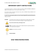
PVI 3000S, 4000S, 5000S, 5300 Series Inverters IMPORTANT SAFETY INSTRUCTIONS In this manual “inverter” or “inverters” refers to the inverter models: PVI 3000S, PVI 4000S, PVI 5000S, and PVI 5300 unless one of the specific models is noted. This manual contains important instructions that shall be followed during installation and maintenance of the PVI inverter.
PVI 3000S, 4000S, 5000S, 5300 Series Inverters IMPORTANT SAFETY INSTRUCTIONS • All electrical installations shall be performed in accordance with the local, American and Canadian electrical codes. • The inverter contains no user serviceable parts. Please contact Solectria Renewables or a Solectria Renewables authorized system installer for maintenance. See Appendix at the end of this manual for Solectria Renewables contact information.
PVI 3000S, 4000S, 5000S, 5300 Series Inverters Table of Contents 1.0 Introduction ...................................................................................................................................... 7 2.0 Site Preparation and Inverter Placement ....................................................................................... 11 2.1 3.0 Inverter Positioning and Mounting .............................................................................................
PVI 3000S, 4000S, 5000S, 5300 Series Inverters 10.2 Appendix B – String Sizing Tool ................................................................................................... 64 10.3 Appendix C – Contact Information.............................................................................................. 64 10.4 Appendix D – Authorized Distributors ........................................................................................ 64 10.5 Appendix E – Positive Grounding Option .....
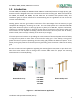
PVI 3000S, 4000S, 5000S, 5300 Series Inverters 1.0 Introduction The PVI 3000S, PVI 4000S, PVI 5000S and PVI 5300 are residential/commercial single phase, gridtied PV inverters designed to be inter-connected to the electric utility grid. With this manual the PVI 3000S, PVI 4000S, PVI 5000S, and PVI 5300 can be installed and operated safely. This installation guide is used as reference for commissioning and as a guideline on how to use the inverter most effectively.
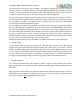
PVI 3000S, 4000S, 5000S, 5300 Series Inverters The string PV concept The use of string PV concept significantly reduces the cabling costs on a photovoltaic system. The use of strings of several PV modules in series and multiple parallel strings of PV modules has proven advantageous by delivering a high operating voltage to the inverter. This advantage results in a higher system efficiency.
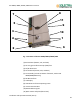
PVI 3000S, 4000S, 5000S, 5300 Series Inverters The housing and heat sink for the PVI 3000S - PVI 5300 is manufactured using an aluminium extrusion with an anti-corrosion finish. The housing is NEMA 3R compliant to be resistant to rain and snowfall. The heat sink and fan are designed in such a way that operation of the inverter is possible at ambient temperatures of -13° F (–25° C) to +131° F (+55° C) at full rated power.
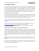
PVI 3000S, 4000S, 5000S, 5300 Series Inverters 8 7 11 5 9 3 10 4 1 6 2 Fig. 1.
PVI 3000S, 4000S, 5000S, 5300 Series Inverters 2.0 Site Preparation and Inverter Placement The inverter is comprised of a rainproof NEMA 3R industrial enclosure containing electrical and electronic components. NOTE: If the inverter is mounted outside, during the installation process and in case of rain, do not open the inverter. Criteria for device mounting: • Because the inverter is in a NEMA 3R enclosure, the inverter can be mounted outdoors.
PVI 3000S, 4000S, 5000S, 5300 Series Inverters CAUTION: Please follow these guidelines: • The inverters weigh up to 60 lbs (27.2 kg) depending on inverter model. Be sure to use a mounting method that will safely hold this weight. Refer to Table 9.3.1 for specific weights for each inverter model. • The ambient temperature must be between –13oF and +131oF (–25oC and +55oC) for full power, and continuous operation.
PVI 3000S, 4000S, 5000S, 5300 Series Inverters 2.1 Inverter Positioning and Mounting Correct mounting position for the inverter is vertical with back of inverter mounted to a wall. Figure 2.1.1 – PVI 3000S-4000S Dimensional Diagram Figure 2.1.
PVI 3000S, 4000S, 5000S, 5300 Series Inverters Figure 2.1.3 – Inverter clearances WARNING: Severe injury or death could occur if the inverter mounting fails and the unit tips over or falls on a person. NOTE: The weight of the inverter will exert an added load to the wall where mounted. Be sure to verify proper load capacity of mounting surface.
PVI 3000S, 4000S, 5000S, 5300 Series Inverters 3.0 Installation WARNING: Before installing the inverter, read all instructions and caution markings in this manual and on the inverter as well as on the photovoltaic modules. WARNING: Electrical installation shall be performed in accordance with all local electrical codes and the National Electrical Code (NEC), Canadian Electrical Code for Canada (CEC).
PVI 3000S, 4000S, 5000S, 5300 Series Inverters 3.2 Removing Inverter from Cardboard Box and Moving Inverter Into Place WARNING: The inverter may tip over if improperly moved, potentially causing damage to equipment, personal injury or death. After taking the inverter out of the cardboard box, you will find the mounting bracket in the bag behind the heatsink. First, the mounting bracket needs to be picked up from the inverter, as shown in Figure 3.2.1. Figure 3.2.
PVI 3000S, 4000S, 5000S, 5300 Series Inverters Figure 3.2.2 – The Mounting Bracket with dimensions Use the mounting bracket as a template to mark the locations on the wall where holes should be drilled. After drilling the holes, the mounting bracket should be fastened to the wall with screws or screw-anchors. The height of the anchor head
PVI 3000S, 4000S, 5000S, 5300 Series Inverters Once the mounting bracket is fastened to the wall, then the inverter and the wiring box can be hooked onto the mounting bracket and slipped down into place. Make sure the lower lip on the bracket hooks into the window on the back of the inverter as shown in Figure 3.2.4. Slide the mounting hooks on the inverter over the hooks on the mounting bracket.
PVI 3000S, 4000S, 5000S, 5300 Series Inverters After the inverter is hooked properly on the bracket, secure it with screws at the bottom flange as shown in Figure 3.2.5. Figure 3.2.
PVI 3000S, 4000S, 5000S, 5300 Series Inverters 4.0 DC Connections from the PV Array and AC Connections to the Electrical Utility Grid * Equipment grounds, grounding electrode conductor and ground fault detector/interrupter not shown Figure 4.0.1 Simplified Electrical Connection Diagram WARNING: All electrical installations shall be performed in accordance with all local and national electric codes.
PVI 3000S, 4000S, 5000S, 5300 Series Inverters Lightning and Surge Protection: The inverter is designed with certain protections against surges in voltage including certification to UL1741/IEEE1547 /CSA22.2#107.1 / FCC Part 15B (including ANSI/IEEE 62.41/62.42 as required in the NY SIR), however added protection and solid grounding provisions are important for best protection against utility surges and surges created by indirect lightning strikes.
PVI 3000S, 4000S, 5000S, 5300 Series Inverters AC Circuit Breakers: A dedicated AC circuit breaker in the home or building circuit panel is required for the PV inverter. Every PVI requires a 208/240V AC rated 2–pole circuit breaker. The following is a table showing the appropriate circuit breaker for the PVI 3000S, 4000S, 5000S, and 5300 (based on number of Amps). PV Inverter Model Circuit breaker used (Amp) for 240V and 208V 4.
PVI 3000S, 4000S, 5000S, 5300 Series Inverters OFF ON Figure 4.1.1 – Turn the DC/AC Disconnect Switch off Figure 4.1.
PVI 3000S, 4000S, 5000S, 5300 Series Inverters After the wiring box cover is removed, the conduit hole covers can be removed (or KOs in other locations punched out) as shown in the Figure 4.1.3, for the DC and AC conduits which will enter and exit these locations. Holes are pre-punched (and shipped with hole covers) for 1” conduit fittings on the left and right sides of the wiring box, these holes are centered at 2.5” from the wall mounting surface.
PVI 3000S, 4000S, 5000S, 5300 Series Inverters Fuse bypass terminal(s) 1 Negati ve ground 1 Positvie ground PV String Fuse AC Terminal Block Ground Bar GFDI Fuse RJ45-L RJ45-R Figure 4.1.4 - Wiring Box (Front and Bottom View). Before wiring the PVI 3000S-5300 inverter, the installer must determine the grid connection/ utility configuration that the inverter will be connected to. The PVI 3000S-5300 inverter is default set for utility interconnection with a neutral connection.
PVI 3000S, 4000S, 5000S, 5300 Series Inverters P1 P2 P3 P1 P2 P3 J210 Figure 4.1.
PVI 3000S, 4000S, 5000S, 5300 Series Inverters Figure 4.1.6 –Utility Configurations 4.2 AC Wiring WARNING: Reconfirm that the circuit breaker to the grid/utility is switched OFF before connecting the power wires from the breaker to the inverter AC terminal block. Use #10 AWG to #6 AWG, 90 °C (194 °F) copper wire for all AC wiring connections to the PVI 3000S-5300 inverters. You must choose the appropriate wire size based on local code requirements.
PVI 3000S, 4000S, 5000S, 5300 Series Inverters L1 wire connected to L1 terminal L2 wire connected to L2 terminal N terminal Equipment ground wire connected to ground bar Figure 4.2.1 – AC Terminal Block for AC Wiring Connections • • • • • • Connect the AC equipment GND wire to the screw of the ground bar labeled Connect the white N wire to the terminal labeled N of the AC terminal block. Connect the L1 wire to the terminal labeled Line1 of the AC terminal block.
PVI 3000S, 4000S, 5000S, 5300 Series Inverters Wiring inverters in parallel PVI 3000S-5300 inverters can be connected in parallel when more power is needed. In the parallel configuration, each inverter shall connect to its own PV array. Do not connect one PV array to more than one inverter. This will cause the inverter to function abnormally. Correct Configuration from DC Side Figure 4.3.1 Parallel configuration of inverters is done on the AC side not the DC side.
PVI 3000S, 4000S, 5000S, 5300 Series Inverters The wiring box of the PVI 3000S-5300 inverter is designed with a pair of DC terminal blocks which support up to four (4) independent PV strings to be fused and connected in parallel in the wiring box and then fed into the inverter (or 3 fused inputs in the case of the PVI 3000S). The PVI 3000S5300 inverter is shipped with up to four (4) 15A, 600Vdc PV string fuses in the wiring box for the PV strings.
PVI 3000S, 4000S, 5000S, 5300 Series Inverters WARNING: Polarities of each DC input voltage from a PV string shall be connected correctly to the “+” (positive) and “–” (negative) terminals of a pair respectively. The DC voltage must be less than 600V in any condition. WARNING: The inverter is listed for no backfeed current into the PV array. However, the ampacity of the PV strings must be calculated when determining proper PV combiner fuse value to prevent fire hazard.
PVI 3000S, 4000S, 5000S, 5300 Series Inverters Termination ON/OFF RS232 Termination RJ45-L RJ45-R Figure 4.4.1 – Position of the Communications Ports and Termination Switches Figure 4.4.2 – RJ-45 Pinouts and Signals If RS-485 interface is selected, both RJ-45 connectors will be used for the daisy-chained/cascaded RS-485 connections shown in the Figure 4.4.3.
PVI 3000S, 4000S, 5000S, 5300 Series Inverters WIH-020081 RS485 Daisy chain To gateway or computer WIH020082 Figure 4.4.3 – RS-485 Connection Description Cable, RS485 comm. PVI 3000S5300 Cable, RS485 daisy chain PVI 3000S-5300 Part Number Typical Use Length WIH-020082 RS485 cable for communication 7 ft gateways WIH-020081 RS485 jumper cable, for 3000S- 30 in. 5300 inverter-to-inverter Table 4.4.4 – Standard Cables available for RS232 and RS485 communication 4.
PVI 3000S, 4000S, 5000S, 5300 Series Inverters NOTE: Make sure all tools, parts, etc. are removed from the vicinity of the inverter before turning on. WARNING: Make a final check of all AC and DC wiring to the inverter and in the system before turning on. NOTE: With the PV modules connected and inverter disconnects still off, perform a final check of the PV voltage and polarity once more using a digital volt meter and probing the positive (+) and negative (-) PV connections.
PVI 3000S, 4000S, 5000S, 5300 Series Inverters into the grid. The LCD display and LED indicators on the front of the inverter provide valuable inverter operating information. 6.1 LCD Display Figure 6.1.1 – LCD Display The green LED "Power" shows the current operating condition. The yellow LED "Error" indicates whether there is an internal or external fault present and whether the AC grid back-feed has been interrupted. The red LED "Ground Fault" shows if a ground fault is present.
PVI 3000S, 4000S, 5000S, 5300 Series Inverters 6.2 LED Indicators LED indicators Green Yellow Red Green Yellow Red Green Yellow Red Green Yellow Red Green Yellow Red Green Yellow Red Green Yellow Red Green Yellow Red Green Yellow Red Green Yellow Red Green Yellow Red Operating status Initialization Description The PVI 3000S-5300 is initializing. System Check mode The inverter is in System Check mode. Monitor mode The inverter is in Monitoring mode.
PVI 3000S, 4000S, 5000S, 5300 Series Inverters 6.3 LCD Display Messages The PVI 3000S-5300 inverter is supplied ready to operate so there are no settings that need to be made by the user for fully automatic operation. The device comes standard with an LCD display on which various data can be read. All indicated data is only an indication and has tolerances of up to ± 5%. The PVI 3000S-5300 inverter has a 16 x 2 LCD to show the operating status, input/output data, and error messages.
PVI 3000S, 4000S, 5000S, 5300 Series Inverters S / N BR XXXXXXXXXXXX XXXXX ID XXX 3 seconds ↓ Then three (3) seconds later, it displays the setting of the nominal grid voltage configuration. The grid type setting of 208/240 with neutral is used as the display example shown below. For the grid type setting, please refer to Section 4 Wiring the Inverter.
PVI 3000S, 4000S, 5000S, 5300 Series Inverters Then three (3) seconds later, it displays the setting of the VacH which is the phase-to-phase (rms) high threshold voltage setting at which point the inverter disconnects itself from the grid when abnormally high phase-to-phase AC voltage is detected. Also, the setting of the clearing time which is the total duration of time to disconnect the output from the AC grid is displayed.
PVI 3000S, 4000S, 5000S, 5300 Series Inverters Va cH L im i t L -N XXX . XV 3 seconds ↓ Then the setting of the re-connection time will be displayed. The re-connection time is the duration of delay time for the inverter to re-connect to the grid after the fault(s) is(are) cleared. Vp vS t a r t XXX . XV Re c o n n e c t XXX s 3 seconds ↓ Waiting Mode Display After the basic information of the inverter is displayed, the system enters the System Check mode which is indicated on the LCD.
PVI 3000S, 4000S, 5000S, 5300 Series Inverters XXX seconds and then show the measured data of the DC input voltages and the existing voltage and frequency on the grid side. Mo d e Mo n i t o r i n Ne x t Co n n e c t g XXX s 3 seconds ↓ Vp v XXX V 3 seconds ↓ Va c F a c XXX . XV XX . XH z 3 seconds ↓ During the monitoring mode, if DC input voltages fall under the PV start voltage setting, the system stays in this mode and shows the information as follows.
PVI 3000S, 4000S, 5000S, 5300 Series Inverters Va c XXX . XV F a c XX . XH z 3 seconds ↓ After the system enters the grid feeding mode, it will show the following information in order and repeat this until the system goes to another operating mode. The first screen shows the current operation mode. Mo d e G r i d / MP P 3 seconds ↓ The next messages are the up-to-minute data of the DC input voltages and the AC output voltage.
PVI 3000S, 4000S, 5000S, 5300 Series Inverters The next message shows the cumulated energy in kWh and period of time in hours for the inverter delivering the power to the grid since the inverter has been power on and operated for today. E t o d a y XXX . X H t o d a y XX . X kWh Hr 3 seconds ↓ The next message shows the cumulated energy in kWh and period of time in hours for the inverter delivering the power to the grid up-to-date since the inverter has been installed and operated. Ea c XXXXXX .
PVI 3000S, 4000S, 5000S, 5300 Series Inverters Mo d e De r a t i n g P a c Mo d e De r a t i n g Va cH There are three possible warning messages that may be displayed with different failures. These messages occur in grid feeding mode. When EEPROM message is displayed, the system is unable to access the EEPROM. The COMM message means a failure of the communication function. The FAN BLOCK message shows that the fan has stopped running. These warnings could appear one after the other.
PVI 3000S, 4000S, 5000S, 5300 Series Inverters 3 seconds ↓ Mo d e e r r o r F a u l t me s s a g e 3 seconds ↓ There are several error messages that show the detailed conditions that cause the system to go into the fault mode, such as the messages shown below that show that the frequency of the AC grid is too high (H) or too low (L). After three (3) seconds, the message shows the present frequency and the frequency that caused the system to go into the fault mode.
PVI 3000S, 4000S, 5000S, 5300 Series Inverters The message below shows the PV DC voltage is too high…. Mo d e F a u l t Vp vH 3 seconds ↓ T r i p a t XXX . XV P r e s e n t XXX . XV 3 seconds ↓ The following message presents that the AC line1 and/or line2 voltage (refer to the neutral) is/are too high (H) or too low (L)…. Mo d e F a u l t Va cL1 X Va cL2 X X: H or L 3 seconds ↓ The messages for the idle mode are as follows.
PVI 3000S, 4000S, 5000S, 5300 Series Inverters Solectria PVI 4000S Figure 6.3.
PVI 3000S, 4000S, 5000S, 5300 Series Inverters 7.0 Troubleshooting and Inverter Messages Identifying and resolving faults The PVI 3000S-5300 is fitted with a self-diagnostic system, which can recognize a majority of possible faults and show these on the display. This allows the operator to rapidly identify possible problems in the solar inverter or system. Please refer to Table 7.1.1 for a thorough explanation of fault codes, modes, etc. These indicate both internal errors and external faults.
PVI 3000S, 4000S, 5000S, 5300 Series Inverters Error Message GridNA No AC voltage is detected. Drift Fac Islanding is detected. VacH The AC voltage of utility is above the upper limit. VacL The AC voltage of mains utility is below the lower limit. FacH The frequency of AC voltage of the utility is above the upper limit. FacL The frequency of AC voltage of the utility is below the lower limit. VpvH The DC voltage of PV array is above the upper limit.
PVI 3000S, 4000S, 5000S, 5300 Series Inverters Imax_AC Over current on the AC side. InvTempMax The internal temperature of the inverter exceeded the safe operating limit. Relay Open Relay Close VacL1 H Relay test failed. VacL1 L The voltage between L1 and neutral is under the lower limit. VacL2 H The voltage between L2 and neutral is over the upper limit. VacL2 L The voltage between L2 and neutral is under the lower limit. The voltage between L1 and neutral is over the upper limit.
PVI 3000S, 4000S, 5000S, 5300 Series Inverters MOV Fault, AC High voltage protection function failed on the AC side. MOV Fault, DC High voltage protection function failed on the DC side. GFDI The GFDI Fuse is open or blown. DCInjectCurH Too much DC current injected into the AC grid is detected. VdcbusH Internal DC bus voltage is above the upper limit. Internal COMM Internal communication failed. Internal watchdog function triggered. Watchdog Internal watchdog function triggered.
PVI 3000S, 4000S, 5000S, 5300 Series Inverters Temp. Sensor Offset check for grid monitoring failed. Turn off the inverter and restart. If the error re-occurs Contact installing company or Solectria Renewables Turn off the inverter and restart. RAM Test The internal temperature sensor failed. If the error re-occurs Contact installing company or Solectria Renewables Turn off the inverter and restart. EEPROM Test Memory failed If the error re-occurs System Error EEPROM test failed.
PVI 3000S, 4000S, 5000S, 5300 Series Inverters Ibuck Over Internal converter over current Converter Error DC/DC hardware failed. Turn off the inverter and restart. If the error re-occurs Contact installing company or Solectria Renewables Turn off the inverter and restart. If the error re-occurs Contact installing company or Solectria Renewables Table 7.1.1 – LCD Error messages 7.
PVI 3000S, 4000S, 5000S, 5300 Series Inverters WARNING: EXTREME SHOCK AND FIRE HAZARD! FAILURE TO FOLLOW THE FOLLOWING PROCEDURE CAN RESULT IN SERIOUS SHOCK, FIRE DAMAGE AND WILL VOID INVERTER WARRANTY! WARNING: PV arrays are always energized when exposed to light, therefore hazardous voltage is still present on the terminal blocks and the PV string fuse holders even when the DC/AC disconnect switch is switched OFF. Please cover the PV arrays with opaque (dark) materials during PV string fuse replacement.
PVI 3000S, 4000S, 5000S, 5300 Series Inverters 8.0 Product Warranty & RMA Policy 8.1 Warranty Policy The Solectria Renewables Warranty Policy is stated below. Solectria Renewables Warranty Coverage: Solectria Renewables Limited Warranties are provided by Solectria Renewables, LLC. ("Solectria Renewables") and cover defects in workmanship and materials. Solectria Renewables’ price for the products is based on inclusion of these limited warranty provisions and disclaimers.
PVI 3000S, 4000S, 5000S, 5300 Series Inverters What will Solectria Renewables do? Solectria Renewables will, at its sole option, repair or replace the defective product free of charge, provided that Solectria Renewables is notified of the product defect within the Warranty Period for the product, and provided that Solectria Renewables, through inspection, establishes the existence of such a defect and that it is covered by the Limited Warranty.
PVI 3000S, 4000S, 5000S, 5300 Series Inverters Reimbursement for contracted services: Solectria Renewables will submit a purchase order to the designated service personnel before work is performed. This purchase order will cover time expected for the required service and most likely an allocation for travel time. Direct returns may be performed according to the Solectria Renewables Return Material Authorization Policy.
PVI 3000S, 4000S, 5000S, 5300 Series Inverters e) The product, if its original identification (trademark, serial number) markings have been defaced, altered, or removed; f) The product, if it has been damaged in shipping (unless approved in writing by Solectria Renewables); g) Any installation and operation beyond the scope covered by relevant safety regulations (UL1741, NFPA 70, etc.); h) Third party monitoring equipment. i) Failure to perform Preventative Maintenance may void the warranty.
PVI 3000S, 4000S, 5000S, 5300 Series Inverters Exclusions of the Policy: Installation and Operation Manual If your product is a consumer product, the applicable law may not permit exclusion of implied warranties. To the extent permitted by the applicable law such warranties are limited to the duration of this Limited Warranty.
PVI 3000S, 4000S, 5000S, 5300 Series Inverters Preparing the product for shipping: 1) Package the unit safely, preferably using the original box and packing materials. Please ensure that your product is shipped fully insured in the original packaging or equivalent. This warranty will not apply where the product is damaged due to improper packaging. 2) Include the following: a. The RMA number supplied by Solectria Renewables clearly marked on the outside of the box. b.
PVI 3000S, 4000S, 5000S, 5300 Series Inverters 9.0 Technical Data Input (DC) from PV array: • Maximum open circuit voltage of PV array is 600V DC WARNING: NEC 690-7 must be followed to calculate the maximum number of PV modules allowed for a maximum inverter open circuit voltage (OCV) of 600V DC in extreme cold temperatures for the installation location. The open circuit voltage of PV modules depends on the cell temperature and the solar irradiation.
PVI 3000S, 4000S, 5000S, 5300 Series Inverters 9.2 Output AC Specifications The PVI 3000S-5300 is designed to feed power into a standard 60Hz, 240 or 208V AC utility service or 208V AC provided within a facility by a step down transformer (for example, from 480V AC service). As required by NEC, there must be a dedicated 2-pole circuit breaker for the PV inverter connection. This circuit breaker (and wiring) must have a rating of 20, 25 or 30A depending on the model.
PVI 3000S, 4000S, 5000S, 5300 Series Inverters Figure 9.3.2 – DC Voltage and AC Output 7~8 digit: Produce month (MM) 6~7 digit: year (YY) Table 9.3.
PVI 3000S, 4000S, 5000S, 5300 Series Inverters 10.0 Appendices 10.1 Appendix A – PVI 3000S, PVI 4000S, PVI 5000S, PVI 5300 Data Sheet http://www.solren.com/downloads/PVI3000-7500_datasheet.pdf 10.2 Appendix B – String Sizing Tool http://www.solren.com/stringSizing.html 10.3 Appendix C – Contact Information Solectria Renewables LLC 360 Merrimack Street Building 9, 2nd floor Lawrence, Massachusetts 01843 USA Tel: 978.683.9700 Fax: 978.683.9702 Sales/ general info: inverters@solren.
PVI 3000S, 4000S, 5000S, 5300 Series Inverters • • • • • • • • • • • Ensure that the inverter is off and de-energized from both AC and DC sides. Open the wiring box and inverter cover. As shown in Figure 10.5.1, the JP14 and JP15 jumpers need to be placed at the higher positions to set to positive grounding. The red DC wire, that connects the inverter board to the wiring box, needs to be connected to “Grounded” DCIN- terminal on the Inverter board.
PVI 3000S, 4000S, 5000S, 5300 Series Inverters JP15 JP15 JP14 1 Positvie ground 1 Negative ground JP14 1 Negative ground 1 Posit vi e ground Red wire connected to Black wire connected to DCINDCIN+ Figure 10.5.1 – Positive Ground Setting and DC Wire Connections connect to PV+ Negativ e ground 1 Positv ie ground 1 UNGROUNDED CONDUCTOR GROUNDED CONDUCTOR Figure 10.5.
PVI 3000S, 4000S, 5000S, 5300 Series Inverters 10.6 Appendix F – Weatherproof Shield for Wind-Driven Snow and Rain The weather proof shield is to be installed on inverters when the chance of rain, snow or severe weather may occur. Examples of installations needing the shields are units installed on trackers or units installed outdoors, fully exposed to elements and in climates where severe weather can occur. • • Remove the (8) eight screws used to fasten the inverter cover.
PVI 3000S, 4000S, 5000S, 5300 Series Inverters 10.6 Appendix G – PVI 3000S-5300 PV Inverter Fault Report Form Basic information Model (i.e.
PVI 3000S, 4000S, 5000S, 5300 Series Inverters 10.7 Appendix H – UL1741 / IEEE 1547 / CSA22.2#107.