OPERATING INSTRUCTIONS PRotEct PV 4600 on-gRid solaR inVERtER En Version 17.03.
Contents Read this User Manual before you start 3 1. Safety Instructions 4 2. Limited Warranty 5 3. 3.1 3.2 3.3 Overview Introducing the grid-connected PV System Introducing the Grid PV System Front Panel LEDs 8 8 9 10 4. Features 11 5. 5.1 5.2 5.3 5.4 5.5 5.6 Installation Inside Protect PV 4600 Package Mounting your Protect PV 4600 Connecting the AC-Output Cable Connecting the PV-Panel Connecting to the connection unit Installation checklist 12 12 12 17 20 21 22 6. 6.
Read this User Manual before you start Congratulations for purchasing your Protect PV 4600 grid-connected PV-Inverter from AEG Power Solutions GmbH (referred to in this manual as “PV-Inverter”, or simply the “device”). This PV-Inverter is a highly reliable product due to its innovative design and perfect quality control. The device is dedicated to high-demand, grid-linked PV systems. This manual contains important information regarding installation and safe operation of this unit.
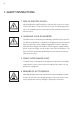
1. Safety Instructions 1. Risk of Electric Shock: Alternating Current (AC) and Direct Current (DC) sources are terminated in this device. To prevent risk of electric shock during maintenance or installation please ensure that all AC and DC terminals are disconnected. 2. Handling your PV-Inverter: The PV-Inverter should only be handled by qualified service personnel. When the PV-panel is exposed to sunlight and connected to the device, it generates a DC voltage charging the DC link capacitors.
2. Limited Warranty The limited warranty provided by AEG Power Solution (“AEG PS”) in this Statement of Warranty applies only to Equipment purchased for residential, commercial or industrial use in the ordinary course of the business. Terms of warranty AEG PS warrants that it is sufficiently experienced, properly qualified, registered, licensed, equipped, organized and financed to perform the Work in compliance with the terms of this Agreement.
Any parts furnished under this warranty may be new or factory-remanufactured. Repair or replacement of a defective Equipment or part thereof does not extend the original warranty period. The AEG PS reserves the rights to modify if necessary the mechanism of the equipment in order to fulfil this Agreement. Warranty claims procedure Should you be experiencing technical issues with your inverters, please have your installer or reseller report the case to the country specific AEG PS hotline.
of all other warranties and remedies. The warranties set forth above, constitute sole liability of AEG PS and purchaser’s exclusive remedy for any breach of such Warranties. The warranties extend only to purchasers and are not extended to any third parties.
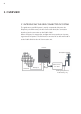
3. Overview 3.1 Introducing the grid-connected PV System The grid-connected PV System is mainly composed of 4 parts: the PV-panels, the PV-Inverter, the AC-Connection Unit (the connection Interface) and a connection to the Public Grid. When a PV-panel is exposed to sunlight and connected to an inverter, it generates DC power. The PV-Inverter converts DC to AC and feeds in to the Public Grid via the AC-Connection unit.
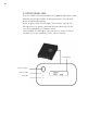
3.2 Introducing the Grid PV System (7) F ront LCD Display Panel (3) 3-pairs of DC inputs (1) Connection Panel (2) Heat-sink (6) RS232 Connector (4) AC Output (5) O ptional Communication Port with Cover Protect PV 4600 Inverter (1) Connection Panel: The connection panel contains DC and AC terminals, and communication ports as detailed below.
3.3 Front Panel LEDs There are 2 LED’s on Protect PV 4600, one is green and the other is red. Normally, only the green LED is on during operation. The indicated status are explained as follows: Power on (green LED): The LED lights, if Protect PV is running. The LED lights not, if no power is provided to Protect PV inverter. In this case, Protect PV 4600 is in shutdown mode. Fault (red LED): The LED lights, if the inverter is in “fault” or “failure” condition.
4.
5. Installation 5.1 Inside Protect PV 4600 Package The following items are included in your Protect PV 4600 Package: (1) Protect PV 4600 PV-Inverter (2) Installation and Operation Manual (3) 4 Mounting Screws and 4 Blade receptacle (4) 2 Safety-lock screws (5) 3-hole Rubber Bushing (6) Mounting Bracket 5.
Mounting Protect PV to the wall 1. Choose a dry place, out of direct sunlight with ambient temperature between 0 and 40 °C. 2. Select a wall or solid, vertical surface which is strong enough to support the inverter. 3. The PV-Inverter requires adequate cooling space for heat dispersal. Reserve at least 20 cm above and below the inverter.
4.
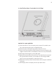
5. To install the device to a narrow surface, mark the 4 central holes at the back of the bracket. Using the CentRal MoUnting holes Upper Central Mounting Holes Lower Central Mounting Holes 6. Drill the 4 marked holes in the wall, and then drive in the 4 Snap Bushings. Now insert the screws and tighten them.
7. Mount the PV-Inverter onto the bracket as illustrated: Safety Lock Screw 8. Insert the Safety Lock screws to fix the PV-Inverter in place. 9. Install the device vertically to ensure the device is properly fixed to the bracket.
5.3 Connecting the AC-Output Cable Connect your PV-Inverter to the AC-Connection unit via the AC-output cable as following steps: AC-Output Connector AC-Output Cable (≥ 2.0 mm²) AC connection unit (consisting of breaker, fuse, terminals etc.) (1) Open the AC-output cover with a screw driver. (2) Draw out the AC Connector set from the Inverter.
(3) U nscrew the cable lock and prepare your AC cable. AC cable lock (4) R emove the rubber plug from inside the AC connector socket. Rubber Plug (no hole in it) (5) Insert the provided rubber bushing with three holes into the AC connector socket.
(6) Now insert the three wires of the AC cable into the bushing holes. (7) Fix the brown wire to L (Line); the blue wire to N (Neutral); and the yellow-green wire to G (Ground). All three wires should be firmly connected. L for Line N for Neutral G for Ground (8) After checking the 3 wires are fixed properly, push the AC-output connection set back in to the Connection Panel. Drive the 4 screws back to fix the set.
(9) N ow screw the Connector Locker in tight to fix the bushing and cable. 5.4 Connecting the PV-Panel (1) First make sure that the maximum open circuit voltage Voc of each PV string is below 750VDC UNDER ANY CONDITION. (2) A lways connect PV-Panel positive (+) terminal to PV-Inverter DC positive (+) terminal, and the PV-Panel negative (-) terminal to PVInverter DC negative (-) terminal. (3) E ach set of PV-Inverter DC terminals takes a maximum DC input of 8.5 A.
(4) To fully optimize the PV DC output set-up, use the following configuration guidelines: (a) For PV DC output less than 8.5 A, use a single pair of PV-Inverter DC terminals. (b) For PV DC output between 8.5 A and 17 A, use two sets of inverter DC terminals. (c) For PV DC output between 17 A and 25.5 A, use 3 sets of inverter DC terminals. 5.5 Connecting to the connection unit The AC connection unit is an interface between your PV-Inverter and the Public grid.
5.6 Installation checklist (1) H igh voltages exist when the PV-Panel is exposed to the sun. Exposed terminals of the PV-Panel are alive, and can cause electric shock. Avoid making physical contact with live parts of the device. (2) A fter the PV-Panels are connected to the PV-Inverter, the output voltage is higher than 100 VDC and the AC grid is not connected to the inverter, the LCD displays “Model= XXXXXX”-> “Waiting”-> “No Utility”. The RED “fault LED” turns on.
The PV-Inverter is feeding power to the grid, and the green LED displays. Before connecting the PV-Panels to DC terminals, make sure the polarity of each connection is correct. An incorrect connection could damage the device permanently.
6. Operation of the Protect PV 4600 LCD Display Function Button Power-on LED Fault LED 6.1 Auto-power The PV-Inverter starts up automatically once DC-power from the PVPanel is sufficient. There are 3 modes of operation. 6.2 Operating Modes 1. Normal In this mode, the PV-Inverter automatically detects the system status and selects the best mode of operation. If the power from the PV-Panel is higher than 150VDC, the supply is converted to AC and fed in to the grid.
2. Fault The PV-Inverter’s intelligent controller continuously monitors the system status. Unexpected conditions such as grid problems or internal failures are displayed on the LCD and the “Fault LED” turns on. Faults are indicated by the red “FAULT” LED. 3. Shutdown At the moment of reduced sunlight, the PV-Inverter automatically shuts down. No power is used from the grid, the LCD display and LEDs on the front panel do not work, and the function button is inactive. 4.
Before connecting PV-Panels to DC terminals, make sure the polarity of each connection is correct. An incorrect connection could permanently damage the device. 6.3 Using the LCD Display Use the Function Button to customize the LCD display settings, or view further information about the internal status of your PV-Inverter. Press the Function Button to change the LCD display. Pressing the Function Button during the ‘Normal’ state displays the grid voltage.
Press the Function Button six times displays the current energy output. Pressing the Function Button seven times displays the Model No. of the Inverter. Pressing Function Button nine times displays the firmware version. Pressing the Function Button a tenth time returns to the status display. Adjusting the LCD Contrast Rapidly press the Function Button during the ‘Normal’ state to display contrast settings. To adjust the contrast settings, press the Function Button again.
After the highest level is reached, the contrast starts to decrease. A few seconds delay and the display automatically returns to its “Normal” display, if the Function Button is not pressed again. Changing the Language Press the Function Button repeatedly until “Set Language” is shown on LCD. Press and hold the Function Button to change the language. Pressing the Function Button cycles through the available languages. After a brief period of inactivity, the display returns “Normal”.
Locking the display To lock the current display (for example frequency), press and hold the Function Button for about a second. The screen displays “Lock” then returns to the previous screen. Pressing the Function Button on the locked display changes to the next screen. After a few seconds of inactivity the display returns to “Normal”. Note After 30 seconds of inactivity, the backlight switches off. Pressing the Function Button reactivates the backlight.
6.4 maximum PowER Point tRacking (mPPt) Due to its advanced design, your PV-Inverter can track the maximum power from any PV-Panel under any condition. If the output power display is stable, your PV-Inverter is converting the maximum power available. If the power reading fluctuates, the device is tracking power changes due to varying levels of sunlight. Individual PV-Panel Output Graph If the output of the PV-Panel is low, the AC power may drift slowly.
6.5 LCD Display Messages Operating conditions Message in English Description Normal Working Status Power off No display PV inverter is totally shutdown, VPV <= 90 V Standby STANDBY 90 V < Input voltage <= 100 V Initialization & waiting READY Input voltage range 100 ~ 150 V during start-up.
LCD Display Message Continued Inverter Fault Consistent failure ERR MICROS The readings of 2 microprocessors are not consistent. Possible cause: CPU and/or other circuit do not function well.
7. Communication Interface 7.1 RS232 Your PV-Inverter is equipped with a versatile communications interface. Use Software Protect PV MONITOR to monitor status of multiple inverters. Firmware upgrades are also available via this interface. Protect PV 4600 is integrated with a DB9 socket for the RS232 interface. Remove the DB9 socket cover before use. Pin assignment of this DB9 socket is stated as below: Pin Signal Assignment 1 N.C. 2 TxD 3 RxD 4 N.C. 5 Common 6 N.C. 7 N.C. 8 N.C. 9 N.C. 7.
8. Troubleshooting The PV-Inverter requires little maintenance. When unexpected situation occurs, please refer to the following table. If the table is insufficient, please call your local dealer. The following table lists common fault messages that display, if the fault LED is lit, and their solutions. System Fault Troubleshooting your PV-Inverter Fault Message Diagnosis and Solution Isolation Fault 1. Check the impedance between PV (+) & PV (-) and ground.
Troubleshooting your PV-Inverter Fault Message Diagnosis and Solution PV Over Voltage 1. Check open PV voltage, if it is too close to or over 750 VDC. 2. If PV voltage is less than 750 VDC and the problem still occurs, please call service. Consistent Fault Inverter Failure SCI Failure 1. Disconnect PV(+) and PV(-) from the input, start the unit again. 2. If it does not work, please call service. Over Temperature 1. The internal temperature is higher than specified normal value. 2.
9. Specifications Modell Protect PV 4600 DC Input Nominal DC voltage 600 VDC Max. PV open voltage 750 VDC MPPT range 125–700 VDC Working Range 100–750 VDC Number of MPP Tracker 3 Max. Input current 8.5 ADC per Tracker AC Output Output power 4600 W Max. power 5000 W Operational Voltage 184–264.5 VAC Operational Frequency 50 Hz Current distortion < 3% Power Factor (cos ϕ) ~1 System Display LCD Display 2 line, 16 Char. Max.
10. Compliance of Standards EMC: DIN EN 50081, part 1 (EMV-interference emission) (EN 55014, EN 60555 part 2, EN 55011 group 1, class B) DIN EN 50082, part 1 (EMV-interference immunity) Grid Interference: DIN EN 61000-3-2 Grid Monitoring: Independent disconnection device (MSD, Mains monitoring with allocated Switching Devices) according to VDEW; DIN VDE 0126-1-1:2006-02 Low Voltage Regulation: DIN EN 50178 (4.98) (VDE 0160) (will be IEC62103) DIN EN 60146 part 1-1 (3.
11. Load Graph and Efficiency Graph The relationship between PV input voltage (VPV) and input power (PPV) is shown in the following example. Once PV input voltage is less than 450 V, the relation of VPV and power is: Ppv(W) = 8.5 x Vpv Example: VPV is 400VDC, the maximum power taken per inverter in one string is 3400 W. Load Graph Ppv(W) = 8.5 x Vpv The typical efficiency chart related to VDC and PAC is shown below. Note Results may vary due to test equipment tolerances and product differences.
OPERATING INSTRUCTIONS, 8000022286 EN, 07/12 - V1 Due to our policy of continuous development, the data in this document is subject to change without notice. AEG is a registered trademark used under licence from AB Electrolux. AEG Power Solutions GmbH Emil-Siepmann-Str. 32 59581 Warstein-Belecke - Germany Phone: +49 (0) 2902 763-520/-290 - Fax: +49 (0) 2902 763-1201 www.aegpowercontrollers.com - www.aegps.