TM SAMIL POWER Expert for PV Grid-tied Inverters SolarRiver PV Grid-tied Inverter Product Manual SP-SR-V8-EN English
Copyright Declaration The copyright of this manual belongs to Samil Power Co., Ltd. Any corporation or individual should not plagiarize, partially copy or fully copy it (including software, etc.), and should not reproduce or distribute it in any form or by any means. All rights reserved. Samil Power reserves the right of final interpretation. This manual is continuously updated based on user feedback. Please check our website www.samilpower.com for the latest version.
CONTENTS 1 Notes ................................................................................................................................ 03 1.1 Scope ................................................................................................................................... 03 1.2 Target Group ......................................................................................................................... 03 1.3 Symbols Used ...........................................................
Notes & Safety 1 Notes This manual is an integral part of the inverter, Please read the product manual carefully before installation, operation or maintenance. Keep this product manual for future reference. 1.1 Scope of Validity This manual is an integral part of the inverter. Please read this manual carefully before installation, operation or maintenance and it safe for future reference.
Safety PV Modules Grid-tied Inverter Grid Figure 1 Solar PV Grid-tied System 2.2 Important Safety Instructions Danger! Danger to life due to high voltages in the inverter! All work on the inverter must be carried out only by qualified personnel. • The appliance is not to be used by children or persons with reduced physical sensory or mental capabilities, or lack of experience and knowledge. • Children should be supervised to ensure that they do not play with this appliance.
Safety Symbol Explanation 5 min Danger to life due to high voltages in the inverter! There is residual voltage in the inverter. The inverter requires 5 minutes to discharge. • Wait 5 minutes before you open the upper lid or the DC lid. Beware of hot surface. The inverter can become hot during operation. Avoid contact during operation. Danger of high voltages Danger to life due to high voltages in the inverter! Caution, risk of electric shock! Only authorized personnel is allowed to set the DIP switch.
Safety & Introduction ● Do not disassemble the SolarRiver Series inverter. It contains no user-serviceable parts. See warranty for instructions on obtaining service. Attempting to service the SolarRiver Series inverter the user may result in risk of electric shock or fire and will void the warranty.
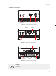
Introduction ● Terminals on the inverter RS232 DC Input AC Output Figure 3 Terminals of PV inverters SolarRiver 1100TL/SolarRiver 1600TL RS485 SF-SW RS232 DC Input AC Output Figure 4 Terminals of PV inverters SolarRiver 2300TL/SolarRiver 3000TL RS485 DC Input SF-SW RS232 AC Output Figure 5 Terminals of PV inverters SolarRiver 3300TL/ SolarRiver 3680TL/ SolarRiver 4400TL/ SolarRiver 5200TL Caution! SF-SW. Risk of electric shock!Only authorized personnel is allowed to set the DIP switch.
Introduction 3.3 Dimensions and Weight ● Dimension Figure 6 SolarRiver 1100TL/SolarRiver 1600TL 328mm 443mm Figure 7 SolarRiver 2300TL/SolarRiver 3000TL 347mm Figure 8 SolarRiver 3300TL/SolarRiver 3680TL/SolarRiver 4400TL/SolarRiver 5200TL ● Weight Table 1 Weight in kilo grams, kg 08 Model SolarRiver 1100TL SolarRiver 1600TL SolarRiver 2300TL SolarRiver 3000TL SolarRiver 3300TL SolarRiver 3680TL SolarRiver 4400TL SolarRiver 5200TL Weight [kg] 11.4 11.4 17.5 17.9 18.9 19.2 19.
Technical Data 4 Technical Data 4.1 Input (DC) Model Max.DC power [W] SolarRiver SolarRiver SolarRiver SolarRiver SolarRiver SolarRiver SolarRiver SolarRiver 1100TL 1600TL 2300TL 3000TL 3300TL 3680TL 4400TL 5200TL 1100 Max.DC voltage [V] Max. input current [A] 1600 2300 3480 500 8.8 4000 4580 5200 20 21 26 550 9.7 Number of MPP trackers/ Strings per MPP trackers 11 13.5 17.5 1/1 MPPT voltage range (at rated powe) [V] 120-425 160-425 Shutdown voltage/ Start voltage 75/100 4.
Technical Data & Function Continued: Ground fault protection Yes Grid monitoring Yes Ground fault current monitoring Yes DC injection monitoring Yes 4.4 General Data SolarRiver SolarRiver SolarRiver SolarRiver SolarRiver SolarRiver SolarRiver SolarRiver 1100TL 1600TL 2300TL 3000TL 3300TL 3680TL 4400TL 5200TL Model Dimensions (W/H/D) [mm] 285 / 385 / 145 328 / 450 / 161 Weight [kg] 11.4 17.5 11.4 347 / 443 / 180 17.9 18.
Installation 【MPPT Mode】 The default setting is MPPT mode, the operation mode will return to MPPT after DC&AC restart. 【Fault Mode】 If any fault/error occurs, inverter will stop delivering power until the fault/error is rectified. Some fault/ error will recover automatically, and others may need manual restart. 【Setting Mode】 Press “Function” key for 5 seconds to get into the Setting mode if DC power exists. Please refer to chapter 7 of the Manual more information. 6 6.
Installation 104.5mm 104.5mm 25.5mm 85mm 126.6mm 85mm 25.5mm SolarRiver 1100TL~1600TL Inverter Backboard 160mm 160mm 120mm 60mm 130mm 192mm 167.5mm 60mm SolarRiver 2300TL~5200TL Inverter Backboard Warning! Ensure that the DC side is not charged before installation or maintenance. If the inverter is powered the capacitors will be charged if after the inverter is turned off, hence it is to wait for 5 minutes to ensure that the capacitors are discharged.
Installation ● ● Not exposed to direct cool air. Not close to television antenna or antenna cable. Inverter needs at least 30cm (see table 2) clearance. If this is not observed, inverter is likely to malfunction high temperature inside the inverter. Samil Power will not cover any damage due to this condition. Position Min. clearance Side 30cm Top 30cm Bottom 30cm Front 10cm Table 2 Minimum clearance needed 6.3 Preparation Following tools are needed for installation.
Installation Step2: Clean all dust outside/inside the hole and ensure the distances between hole are as per requirement. Insert expansion pipes into the holes vertically, use rubber hammer to tap the pipes into the wall completely. Insert the bracket into expansion pipes and use expansion screws to fasten the bracket.
Installation Step3: Use the bracket to install the inverter onto the narrow vertical panel (or wall). Ensure the upper corner of inverter is attached onto the bracket. Step4: Make sure the bracket and the inverter’s right side screw hole are in line and matching well, fix the screw into the hole and screw into the inverter tightly. Step5: If necessary lock the inverter and the bracket with padlock (not included) for safety. 6.
Installation Note! Need not connect the input terminal to optimizer. ● AC Output SolarRiver series inverters are designed for single phase grid. Operating AC voltage range from 180V to 260V (200V-270V for Australia) and the typical frequency is 50Hz. Other operating parameters should comply with local public grid regulations. Table 4 Cable and MCB Requirement Model SolarRiver 1100TL Cable (Cu) 1.
Installation Pressure screw Thread sleeve with sealing ring 10-14mm Socket element sealing ring 6-10mm SolarRiver 2300TL~5200TL SolarRiver 1100TL~1600TL Figure 14 AC Connector details Follow following steps for wiring AC Connectors. Step1: Pass the AC wire through the threaded sleeve and pressure screw (See figure 15). Pressure screw Thread sleeve Figure 15 Step2 : Connect the AC cables as explained below.
Installation Step3: Confirm that all the wires are fixed tightly( Figure 17). Pressure screw Connected wires Thread sleeve Socket element Figure 17 Step4: Fix the threaded sleeve (Figure 18). Pressure screw Socket element Thread sleeve Figure 18 Step5: Fix the pressure screw (Figure 19). Pressure screw Threaded sleeve Figure 19 Step6: Connect AC connector to inverter (Figure 20).
Installation & Operation 6.6 Inverter Start-up • Only start inverter after checking following a. Make sure all the DC and AC breakers and Isolators are in off position. b. AC cable from inverter to connection point is done correct. c. All PV panels are connected to inverter correctly,Unused DC connectors should be sealed using covers provided. • Starting inverter a. Turn ON AC MCB. b. Turn ON DC Isolator and then AC Isolator. c. Inverter will start up automatically when PV arrays generates enough energy.
Operation 7.2 Display Function The function key is used to set the LCD. It can alternate between different parameters and languages. Use Function Key to check and set inverter parameters SolarRiver 4400TL Pac=x.xW Display on normal operation Inverter will change into standby mode when 100V150V, Inverter will change into “Normal State” mode after 180 second start-up time. Waiting Pac=x.xW Checking 180s Pac=x.xW Normal State Pac=x.
Operation Initial State LCD lights up. Normal State Pac=xxxx.xW Displays total Energy. Etotal=xx.xkwh Pac=xxxx.xW Displays n day’s energy. Etoday=.xxxx.xkwh Pac=xxxx.xW Displays the PV voltage. Vpv=xx.xV Pac=xxxx.xW Displays inverter model. SolarRiver 4.4kW Pac=xxxx.xW Displays software version. Ver. V1.00 Pac=xxxx.xW Language setting. Select Language Pac=xxxx.xW Energy today reset. Reset Etoday Pac=xxxx.xW Displays PV current. Ipv=xx.xA Pac=xxxx.xW Displays AC voltage.
Operation (Press Function key to check data will go back to initial state after 10s of inactivity) Lockup function as below: Set language as below: Udc=xx.xV Normal State Pac=xxxx.xW Pac=xxxx.xW Press the Function key for 5 Press the Function key 10 times, seconds, it will be locked. it will display the language setting. Lock Select language Pac=xxxx.x Pac=xxxx.xW Press and hold the Function Key to change language English Udc=xx.xV Pac=xxxx.xW Pac=xxxx.
Operation Continued: Output Voltage Vac=xxx.xV Output voltage Output Frequency Freq.=xx.xHz Output frequency Output Current Iac=xx.
Communication and Monitoring 8 8.1 Communication and Monitoring Communication Interface SolarRiver inverters have communication interface RS485 and /or RS232 depending on model. Output voltage, current, frequency, fault information, etc., can be delivered to a PC or other monitoring equipment via the RS485/RS232. 8.2 Communication types SolarRiver inverters come with one or both of the following types communication facility depending on model.
Communication and Monitoring server Router Figure 24 SolarLog Monitoring Diagram Two types of cable must be prepared when using SolarLog for monitoring multipleinverters. Inverter wiring Find a Ethernet cable with appropriate length. At one end of the cable, strip off about 2 inches of the Ethernet cable sheath. Choose 4 wires (brown,brown white, orange , orange white), and press the 4 wires into pin1 to pin4 of the RJ11 crystal head as below.
Troubleshooting 9 9.1 Troubleshooting Troubleshooting This section contains information and procedures for solving possible problems on SolarRiver series inverters, and provides troubleshooting tips to identify and solve most problems. This section will help narrow down the source of any problems which you may encounter. Please read the following troubleshooting steps. ● Check the warning or fault messages on the System Control Panel or Fault codes on the inverter information panel.
Troubleshooting Continued: Fan Fault 9.2 - Check the fan for any block. - Check fan cables. - If fault persists, contact Samil Power for assistance. Relay Failure - Disconnect PV +ve and –ve input, and re-connect after a short break. - If fault persists, contact Samil Power for assistance. Ground I Fault - Leakage current is too high. - Disconnect DC and AC connector, check equipment on the AC side for concerns and rectify any faults found. - Reconnect the DC input and check operation..
Decommissioning & Contacting Samil Power 10 Decommissioning 10.1 Dismantling the Inverter ● Disconnect the inverter from DC Input and AC output. ● Remove all connection cables from the inverter. ● Remove the inverter from the bracket. 10.2 Packaging If possible, pack the inverter in the original packaging. If original packaging is not available, use an equivalent carton that meets the following requirements. ● Suitable for loads more than 25 kg. ● With handle. ● Can be fully closed. 10.
SAMIL POWER CO., LTD. Marketing & Sales Office Factory Add: Add: No.52,Huigu Innovation Park, Huishan District, Wuxi,Jiangsu Province,P.R.China 214174 Tel: +86 510 83593131 Fax: +86 510 81819678 E-mail:service@samilpower.com http://www.samilpower.com Tel: Fax: No.66 Taihangshan Road, Suyu Economic Development Zone, Suqian City, Jiangsu Province, P.R.