
Technical information


x
List of Figures
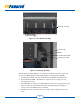
Figure 1-1 PVP250kW and PVP260kW Inverters ...........................................................3
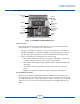
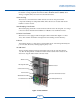
Figure 1-2 Power Module Assembly ................................................................................4
Figure 1-3 Card Cage Assembly .......................................................................................4
Figure 1-4 AC Sub Panel ..................................................................................................5
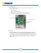
Figure 1-5 AC Distribution PCB ......................................................................................6
Figure 1-6 Comm X PCB .................................................................................................7
Figure 1-7 DC Combiner Sub Panel Shown with 16-Circuit Monitoring Subcombiner .. 7
Figure 1-8 DC Distribution PCB ......................................................................................8
Figure 2-1 Inverter in the De-energized State ................................................................19
Figure 3-1 Inverter Clearances .......................................................................................22
Figure 3-2 DC Subcombiner Box Options .....................................................................26
Figure 4-1 Busbar Connection and Terminal .................................................................. 28
Figure 4-2 Screen Check ................................................................................................29
Figure 4-3 Air Deector Check ......................................................................................29
Figure 4-4 Busbars and Busbar Connection Inspection .................................................29
Figure 4-5 Inspection of Cable Connections ..................................................................30
Figure 4-6 Pull Test of Cable Screw Terminal Connection ............................................30
Figure 4-7 Screen Inspection ..........................................................................................30
Figure 4-8 Checking the Busbar Connections ................................................................31
Figure 4-9 Fan Inspection ...............................................................................................31
Figure 4-10 Air Filter Check ............................................................................................32
Figure 4-11 Bottom Entry Gland Plates - DC Side ..........................................................34
Figure 4-12 Side Entry Gland Plates - AC Side ...............................................................34
Figure 4-13 Conduit Hub Installation ............................................................................... 35
Figure 4-14 DC and Phase Inverter Connections .............................................................39
Figure 4-15 Busbar Connections ......................................................................................40
Figure 4-16 DC Subcombiner Congurations ..................................................................43
Figure 4-17 T-568B Compliant Ethernet Cable ................................................................ 44
Figure 4-18 Comm X PCB Ethernet Port Location .......................................................... 45
Figure 5-1 Comm X PCB in the Data Monitoring Section ............................................50
Figure 5-2 Comm X PCB with Modbus Slave Port Location ........................................50
Figure 5-3 Daisy Chain Layout for RS-485 Network ....................................................51
Figure 5-4 Location of Jumpers J6, J16 and J7 on the Comm X PCB ...........................54
Figure 5-5 Rotary Switches for Setting the Inverter Number.........................................55
Figure 6-1 AC and DC Disconnect Power ON ............................................................... 64
Figure 6-2 Inverter State Diagram ..................................................................................65
Figure 6-3 Display ..........................................................................................................67
Figure 6-4 Startup State Screen ......................................................................................67
Figure 6-5 Power Track State Screens ............................................................................67
Figure 6-6 Fault State Screens ........................................................................................68
Figure 6-7 Warning State Screen ....................................................................................68
Figure 6-8 Disabled State Screen ...................................................................................68
Figure 6-9 Ground Fault Error Message ......................................................................... 69
Figure 6-10 AC and DC Disconnect Power OFF .............................................................70
Figure 7-1 Air Intake Hood ............................................................................................73
Figure 7-2 Air Intake Hood in Raised Position for View of
Blower Intake Filters and Brackets ...........................................................73
Figure 7-3 Card Cage Air Filter ......................................................................................74
Figure 7-4 Example of the Fault Display Screens ..........................................................75