
Technical information


3
PVP250kW & PVP260kW Inverter
Installation & Operation Manual
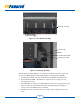
1.4 Major Components and Functional Parts Descriptions
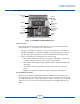
Figure 1-1 PVP250kW and PVP260kW Inverters
Main Enclosure
The modular design of the inverters makes them easy to access and service. The main
enclosure (Figure 1-1) is comprised of two main sections:
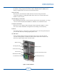
1. The upper compartment contains the power conversion electronics, control Printed
Circuit Boards (PCB), power distribution PCB, power supply and active cooling sys-
tem. The upper right compartment contains the dedicated data monitoring section.
2. The lower and magnetics compartments house the following:
• DC Combiner Sub Panel contains the optional fused subcombiner, optional sub-
combiner monitoring and the positive, negative and ground bars.
• DC Sub Panel with integrated DC ground fault detector interrupter PCB and DC
disconnects.
• AC Sub Panel with AC output ltering, surge protection and AC connection
points.
• Magnetics Compartment contains the isolation transformer and inductors.
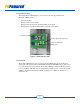
Power Module Assembly
The inverters use Insulated Gate Bipolar Transistors (IGBTs) for converting DC power
into three-phase AC power. The inverters are protected by over-current, over-voltage and
over-temperature detection controls. If a protection system is activated, the power module
will cease power conversion and send an interrupt signal to the Digital Signal Processor
(DSP).
Air Intake
Hood
Power
Module
Assembly
DC
Combiner
Sub Panel
Display
AC Sub
Panel
Revenue
Grade Meter
(optional
feature)
DC Sub
Panel
Data
Monitoring
Section
}