
Technical information


4
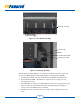
Figure 1-2 Power Module Assembly
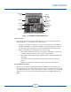
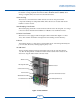
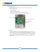
Figure 1-3 Card Cage Assembly
The Card Cage Assembly (Figure 1-3) is designed to enable fast and easy service and
also acts as an EMI shield to ensure signal integrity on the following four PCBs:
1. Communications PCB – Provides serial, internet and Modbus communications.
2. Power Distribution PCB – Distributes the required logic level voltages for use
throughout the inverter.
3. Controller PCB – Contains a powerful DSP that controls sine wave generation, logic
functions and protection activities. All analog and digital inputs and outputs are
routed to the Control PCB and fed to the DSP.
4. I/O PCB – Provides a central location for a range of input, output and control cir-
cuits.
}
Card Cage Assembly
Controller PCB
I/O PCB
Power Distribution PCB
Communications PCB