
Technical information


47
5. Modbus Network Installation
5.1 Overview
PV Powered commercial inverters can communicate via Modbus RS-485 and Modbus
TCP/IP. This chapter explains how to communicate with a PV Powered commercial
inverter on a Modbus network through either RS-485 or TCP/IP. This chapter is written
for PV installers, electricians, controls contractors and Modbus network programmers.
5.2 Modbus Communication Protocol
Modbus is a serial communications protocol and is the most commonly used means
of monitoring and communicating between devices in the PV industry. The Modbus
protocol allows for communication between a Modbus master device and multiple
Modbus slave devices connected to the same network. The physical layer of the Modbus
network is a twisted pair shielded conductor for RS-485 and CAT5 Ethernet for TCP/IP.
5.3 Networking Using the Modbus Option
The following steps are required to set up a Modbus TCP/IP network for your PV
Powered inverter:
• Field Installation Process
This step can be completed onsite by a PV installer or an electrician that does not
have working knowledge of a Modbus network:
• Consult the facility IT administrator for network device installation support
and coordination.
• Install the Modbus network communications cabling.
• Modbus Network Conguration Process
This step can be done onsite or remotely and should be completed by the
Modbus network programmer:
• Set the IP addresses and Port ID for TCP/IP.
• Congure the point maps for slave devices.
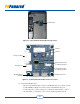
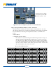
5.4 Modbus TCP/IP Installation Process
Disconnect the power to the inverter before starting the installation.
!
DANGER
AC and DC voltages will still be present at the inverter AC and DC
landing points unless utility connection circuit breaker and PV array
inputs are disconnected.
MODBUS
INSTALLATION