
Technical information


50
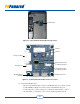
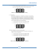
Comm X PCB
Figure 5-1 Comm X PCB in the Data Monitoring Section
Factory Use Only
Ethernet Port
Modbus Master
(inactive)
Switch 1
Switch 2
Master jumpers with
no jumpers installed
Slave jumpers with
no jumpers installed
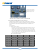
Modbus Slave Port
Figure 5-2 Comm X PCB with Modbus Slave Port Location
C. Connect the Modbus cable.
The end of the Modbus cable connects to the Modbus slave port connector on the
Comm X PCB. See Figure 5-2 for the location of the Modbus slave port.
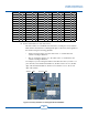
Connect the plus (+) cable to all plus (+) connections and the minus (-) cable to
all other minus (-) connections so they correspond throughout the network.