
User manual


2. Cut a hole in the desired location to allow access for the cable.
3.
Install a water-tight conduit hub connection.
4. Replace the gland plate.
5. Route an Ethernet cable from a network port in the facility that has been
approved by the network administrator through the conduit hub.
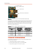
6. Connect the Ethernet cable to the Ethernet port on the communication interface
PCB.
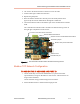
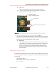
The communication interface PCB is located in the data monitoring section in
the right upper compartment of the inverter.
Inverter control wire harness connectors
Remote disable terminal block
Modbus slave port terminal blocks
RJ45 Ethernet port
Termination jumpers
Address switch
Screws to remove remote disable terminal block
Figure 6‑4. Communication interface PCB in the data monitoring section
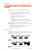
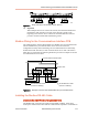
Modbus TCP Network Configuration
TO ASSIGN THE IP ADDRESS AND PORT ID
1. Contact the facility’s IT Network Administrator (or person with similar
responsibilities) to assign an IP address to each inverter. Advanced users can
assign a static IP address.
Contact AE Solar Energy Technical Support for assistance.
2. Set the Modbus master to communicate through port 502.
Advanced Energy® PVP250kW and PVP260kW Inverters
570-1001792-05A Data Monitoring and Controls 6‑7