Installation Manual 10’W x 12’L x 6.5’H Premium Canopys Protective Weather Structures Inc. 5290 Orcutt Road San Luis Obispo, CA 93401 © 2011 - All Rights Reserved PWSsteelbuildings.
PWS has dedicated years of steel building knowledge and construction to creating the highest quality canopy made today. With a little effort following the detailed instructions during assembly, this canopy will provide you with years of enjoyment and unparalleled protection. Contents Safety & Hazards Consideration................................4 Tools Required..............................................................4 Parts List........................................................................
Safety & Hazards Considerations • • • • • • • • • • • • • Check that all tools and canopy components are available prior to erecting structure. Two people are necessary to safely erect the canopy. Do not allow children to play around the assembly area. Protect yourself by wearing protective work gloves, hard hat, safety glasses, and shoes during assembly. Some parts have sharp edges which may cause cuts or lacerations.
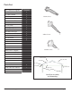
Parts List Part # and Description ( 1 ) Base Rails ( 2 ) End Columns ( 3 ) Center Columns ( 4 ) Roof Truss ( 5 ) Center Roof Truss ( 6 ) Purlins ( 7 ) Eve Trim ( 8 ) Ridge Cap ( 9 ) Rake Trim Left ( 10 ) Rake Trim right ( 11 ) J-Trim ( 12 ) Gable Sheet Metal Kits ( 13 ) Insulation ( 14 ) Roof Sheet Metal Quantity 2 4 2 2 1 6 5 1 2 2 4 6 3 8 Frame Screw Sinker Screw Stitcher Screw Frame Screws – Regular Sinker Screws – Roof Color Sinker Screws – Trim Color Stitcher Screws – Roof Color Stitcher Screws –
Column Inserts Base rail and Terminology PWS -Premier Canopies 1-888-547-8797 Page 5
Canopy Installation Site Preparation It’s important to have the site ready for the installation of the canopy. The frame is designed to be placed either onto a concrete foundation, anchored with concrete piers, or staked into the ground. There is likely more than one way to properly anchor the canopy, however, we provide three different options. Important: If a concrete slab is to be poured, preparing the ground by leveling and compacting may be necessary.
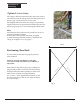
Foundation & Anchoring Option 1: Direct Staking The canopy is delivered with rebar stakes that can be used to either directly stake the canopy down into firm ground or in option 2 page 8 as an anchor for concrete piers. The Simplest method to anchor the canopy is to pound the supplied stakes into the ground with a hammer after the base rails are properly spaced. (See Positioning Base Rails below.) Note: Anchoring the rebar stakes into the ground best serves as a temporary anchoring solution.
Option 2 : Anchor to New Concrete Pier The second simplest method to anchor the canopy frame is to pour concrete piers. Layout the base rails per the previous instruction (see Positioning Base Rails page 7) and mark the locations where the Anchor Stake are to be located. Remove the base rails and dig each hole a minimum of 24” or down to the frost line, whichever is greater (fig 2).
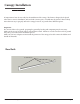
Canopy Frame Assembly Roof Truss Rafter Eve end Eve Face Column Inserts Truss Assembly Step 1 - Verify the placement of the Base rail assemblys for squareness and correct rail separation. Tip: Laying the truss components at least 8 feet in front of the Base rails will help simplify the ease of assembly. Step 2 - In preparation for assembly, stack all the trusses.
64” 32” 3/4” (fig 4) Step 4 - Install the columns to the rafter by slipping them over the column inserts. Check that the columns are at right angles to the rafter by using a framing square as shown (photo 8). You can verify that the columns are square by measuring the distance at the bottom of the columns. This distance should be the same as the width of the frame (10 feet apart). Attach all columns as shown (fig 6). Each leg requires 4 frame screws.
Purlin Assembly Purlins Purlins Assembled Frame (photo 12) Step 1 - The purlins should be with the large holes facing up laying tight next to base rails. Line up the ends of the assembled purlins with the ends of the base rails. Mark next to the holes at the edges of each column (photo 12). Note: Installing purlins (photo 13) It is recommended that you start from the top, working your way down.
Insulation Insulation Note: It is not recommended to install the Insulation on a windy or breezy day as the adhesive will not likely hold in these conditions. Step 1 - Apply the double sided adhesive tape on top of both (photo 16) the outermost purlins from end to end as shown, leaving the tape cover on for now (photo 16). Step 2 - Place the first of 3 sheets of insulation over the canopy, white side facing down. The insulation will be several inches longer than need be on both sides.
(photo 18) (photo 19) Eve Trim Eve trim Step 1 - Begin installing the first Eve trim at the back of canopy frame working forward. Place trim on top of Insulation and end of rafter with drip edge down. Extend it past outside of rafter face 11/4” (photo 20)(fig 8 on page 14). Note: It’s very important to press down firmly to compress the insulation before fastening it down. Otherwise, when the roof sheet is installed, it will tend to cause it to deform.
Roof Sheet Roof sheeting Truss face Warning - Do not attempt to stand on roof panels that have not been attached. Step 1 - The placement of the first sheet is the most critical. J (photo 22) The sheet is not symmetrical and must be started as shown (photo 22) with the short overlap facing out. Make sure the sheet is square to the frame. It must be positioned a set disI tance from the face of the rafter as well as from the eve trim (fig 8)(fig 9).
Note: Double check the 21/2” overhang and make sure the sheet is perpendicular to the purlins. The stitcher screws are only used to fasten sheet metal to sheet metal. Make sure the screws are the correct type and color. Step 2 - Follow the pattern below to fasten the sheet to the purlins (fig 9). Mark the location by measuring out where the screws go before lifting sheet onto the roof (photo 25).
Gable and J-trim Gable kit J-trim Step 1 - Align the bottom of the J-trim with the bottom of the truss cord and extend end of J-trim to eve trim (photo 27). Using frame screws, fasten the J-trim to the face of the truss in from each end 2”. These screws will be removed later. Repeat this step on the other end. Step 2 - The Gable kit comes in five pre-cut pieces per end. (photo 27) (photo 28) Start with the center left section (photo 28).
Sinker Screws Screw Pattern - End Gables (fig 10) Stitcher Screws Sinker Screws Rake Trim Rake trim Step 1 - Locate the left side, uncut Rake trim, and position it as shown in (photo 30). If the roof sheet was fastened in the correct location, the top edge should line up directly in the middle of the peak, and the bottom edge should line up with the roof sheet.
(photo 32) (photo 33) Step 3 - Using the same color stitcher screws as the (photo 34) trim, the first screw should be into the face of the J-trim drilling through the edge of the rake trim as shown in (photo 32) and (photo 33). After verifying that everything is square and in place, fasten a sinker screw down through top edge of the rake trim and down through the roof sheet into the center of the purlin below. Continue on every purlin.
Ridge Cap Ridge Cap Note : The ridge cap attaches in two pieces. Be careful while handling, they can buckle which will leave an undesirable crease. Step 1 - Begin by laying the first ridge cap starting from the back. Align the ridge cap end even with the outside face of the rake trim (photo 37). Using color matched stitcher screws, attach through the edges of the ridge cap into the rake trim on both sides. Align the other end of the ridge cap with the center of roof ridge. Do not attach at this time.
PWS - Premier Canopies 1-888-547-8797 Page 20