
Data Sheet

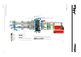


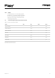
Table Of Contents
- 3.0 Specifications
- 4.0 Block Diagram
- 6.0 Pin Details
- 7.0 ESP32 Peripherals
- 8.0 Programming the device
- 9.0 Boot modes
- 10.0 Power
- 11.0 Memory Map
- 12.0 WiFi
- 13.0 Bluetooth
- 14.0 LoRa
- 15.0 Sigfox
- 16.0 6LoWPAN
- 17.0 Electrical Characteristics
- 18.0 Minimum Recommended Circuit
- 19.0 Mechanical Specifications
- 20.0 Recommended Land Patterns
- 21.0 Soldering Profile
- 22.0 Ordering Information
- 23.0 Packaging
- 24.0 Certification
- 25.0 Revision History

06Version 1.0
6.0 PinDetails
Table 1 – Module pinout
Module
Pin
ESP32
GPIO
Pin
Name
DefaultFunction ADC PWM RTC† Notes
1 – – Reset
Active Low, connected to on–board
button
2 3 P0
RX0
(Programming)
Used by the bootloader and to program
the module
3 1 P1
TX0
(Programming)
Used by the bootloader and to program
the module
4 0 P2 2*
If tied to GND during boot the device will
enter bootloader mode, Connected to the
on–board RGB LED
5 4 P3 TX1 2*
6 15 P4 RX1 2* JTAG TDO, SD card CMD
7 5 –
LoRa/Sigfox radio
SPI CLK
Not recommended for external use
8 27 –
LoRa/Sigfox radio
SPI MOSI
2* Not recommended for external use
9 19 –
LoRa/Sigfox radio
SPI MISO
Not recommended for external use
10 2 P8 2* SD card DAT0
11 12 P9 SDA 2* JTAG TDI
12 13 P10
SCL (I2C) / CLK
(SPI)
2* JTAG TCK
13 22 P11 MOSI
14 21 P12
If tied to 3.3V during boot the device
enters safe boot mode, JTAG MISO
15 36 P13 1 Input only
16 37 P14 MISO 1 Input only
17 38 P15 1 Input only
18 39 P16 1 Input only
19 35 P17 1 Input only
20 34 P18 1 Input only