
Data Sheet


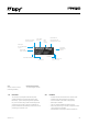
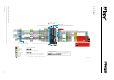


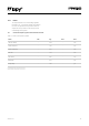
Table Of Contents
- 3.0 Specifications
- 4.0 Block Diagram
- 6.0 Pin Details
- 7.0 ESP32 Peripherals
- 8.0 Programming the device
- 9.0 Boot modes
- 10.0 Power
- 11.0 Memory Map
- 12.0 WiFi
- 13.0 Bluetooth
- 14.0 LoRa
- 15.0 Sigfox
- 16.0 6LoWPAN
- 17.0 Electrical Characteristics
- 18.0 Minimum Recommended Circuit
- 19.0 Mechanical Specifications
- 20.0 Recommended Land Patterns
- 21.0 Soldering Profile
- 22.0 Ordering Information
- 23.0 Packaging
- 24.0 Certification
- 25.0 Revision History

07Version 1.0
6.0 PinDetails
Table 1 – Module pinout
Module
Pin
ESP32
GPIO
Pin
Name
DefaultFunction ADC PWM RTC† Notes
21 32 P19 1
22 33 P20 1
23 26 P21 2* DAC,
24 25 P22 2* DAC
25 14 P23 2* JTAG TMS, SD card SCLK
26 – –
Regulated 3.3V
supply
Output only, do not feed 3.3V into this pin
or you can damage the regulator
27 – – Ground
28 – – Voltage Input Accepts a voltage between 3.5V and 5.5V
– 18 – LoRa reset
– 16 –
External WiFi/BT antenna switch, Low =
on–board, High = U.FL
– 23 – LoRa/Sigfox radio interrupt
– 17 – LoRa/Sigfox radio chip select
† The pins on the RTC power domain can be used during deep sleep, specically GPIO pins will maintain their state while in deep sleep.
* ADC2 is currently not supported in the micropython rmware
6.1 RemappingPins
The ESP32 features comprehensive pin remapping
functionality. This allows peripherals to be mapped
onto almost any available GPIO pins. The above table
merely shows the default assignments. For example, the
default mapping has the SPI and I2C clocks overlapping,
meaning both cannot be used simultaneously without
remapping one to a different pin. For a detailed guide of
what peripheral can be assigned to what pins please read
“Appendix A – ESP32 Pin Lists” of the ESP32 datasheet.