
Data Sheet


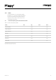
Table Of Contents
- 3.0 Specifications
- 4.0 Block Diagram
- 6.0 Pin Details
- 7.0 ESP32 Peripherals
- 8.0 Programming the device
- 9.0 Boot modes
- 10.0 Power
- 11.0 Memory Map
- 12.0 WiFi
- 13.0 Bluetooth
- 14.0 LoRa
- 15.0 Sigfox
- 16.0 6LoWPAN
- 17.0 Electrical Characteristics
- 18.0 Minimum Recommended Circuit
- 19.0 Mechanical Specifications
- 20.0 Recommended Land Patterns
- 21.0 Soldering Profile
- 22.0 Ordering Information
- 23.0 Packaging
- 24.0 Certification
- 25.0 Revision History

08Version 1.0
7.0 ESP32Peripherals
Table 2 – Peripherals
* Requires an external CAN bus transceiver, we recommend the SN65HVD230 from Texas Instruments.
For a more detailed description of the ESP32 peripherals
along with peripherals not currently supported by our
rmware, please check the ESP32 datasheet.
7.1 RTC
Our modules by default all use the internal RC oscillator
at 150kHz for the RTC. If you require better accuracy/
stability you can connect a 32.768 kHz crystal (or TCXO)
externally on pins P19 and P20 (or P19 for a TXCO)
Peripheral Count Pins
UART 3
Remappable to any GPIO.
Note: P13–18 can only be mapped to RX or CTS since they are input only.
I2C 2 Remappable to any GPIO except P13–18 since they are input only and I2C is bi–directional.
SPI 3
Remappable to any GPIO.
Note: P13–18 can only be mapped to MISO since they are input only.
CAN* 1
Remappable to any GPIO.
Note: P13–18 can only be mapped to RX since they are input only.
JTAG 1 TDO = P4, TDI = P9, TCK = P10, TMS = P24
PWM 1 All GPIO except P13–18 which are input only
ADC 18 Fixed mapping, see Table 1, Only ADC 1 is supported in our micropython rmware.
DAC 2 Only available on P21 and P22
SD 1 DAT0 = P8, SCLK = P23, CMD = P4