
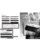
9 Pyle Pro Mixer Owner's Manual


MIC 2
LL
R
GND
L
R
L
R
L
R
L
R
L
R
L
R
LR
Master Booth Rec
BALANCED
OUTPUT
Line 9 Line 8 Line 7 Line 6 Line 5Line 5 Phono 2
/Line 4
LN 4 PH 2 Line 3 Phono 1
/Line 2
LN 2 PH 1 Line 1
CH 5 CH 4 CH 3 CH 2 CH 1
INPUT
FUS E F 50 0mA 250 V
~AC INP UT
VOLT AGE
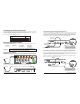
This mixer permits connection of up to nine (9) audio input sources,and two microphones. Such a
system might include, for example:
Please observe
the following:
Do not connect any audio source with a HIGH LEVEL OUTPUT to the
LOW LEVEL PHONO 1 or PHONO 2 mixer audio input jacks (an audio
source output with a volume control is HIGH LEVEL).
Connecting the Mixer Inputs
MIC 2
LL
R
GND
L
R
L
R
L
R
L
R
L
R
L
R
LR
Master Booth Rec
BALANCED
OUTPUT
Line 9 Line 8 Line 7 Line 6 Line 5Line 5 Phono 2
/Line 4
LN 4 PH 2 Line 3 Phono 1
/Line 2
LN 2 PH 1 Line 1
CH 5 CH 4 CH 3 CH 2 CH 1
INPUT
FUS E F 50 0mA 250 V
~AC INP UT
VOLT AGE
LL
R
L
R
L
R
PH 2 Line 3 Phono 1
/Line 2
LN 2 PH 1 Line 1
CH 2 CH
NPUT
If you use a High Level Output Audio Source(s)
in the Phono1/Line2 (and/or Phono2/Line4)
input jack(s), be sure to place the Input Select
switch in the LINE2 (and/or LINE4) position(s)!
NOTE!
Connecting Turntables and Other Level Output Audio Sources
Connect up to 2 turntables to the Phono 1 and Phono 2 input jacks. Please note that Phone 1 and
Line 2 (as well as Phono 2 and Line 4) use the same jacks. The selector switch below the jacks should
be set to Phono position if the jacks are used for phono inputs.
When using a turntable, you should also securely connect its ground wire (usually green or black)
to the Ground screw on the input panel of the mixer.
MIC 2
LL
R
GND
L
R
L
R
L
R
L
R
L
R
L
R
LR
Master Booth Rec
BALANCED
OUTPUT
Line 9 Line 8 Line 7 Line 6 Line 5Line 5 Phono 2
/Line 4
LN 4 PH 2 Line 3 Phono 1
/Line 2
LN 2 PH 1 Line 1
CH 5 CH 4 CH 3 CH 2 CH 1
INPUT
FUS E F 50 0mA 250 V
~AC INP UT
VOLT AGE
Use RCA type
patch cables
LEFT output
RIGHT output
Magnetic cartridge turntable
GROUND wire from turntable
If you use a Turntable in the Phono1/Line2
(and/or Phono2/Line4) input jack(s), be sure
to place the Input Select switch in the PHONO1
(and/or PHONO2) position(s)!
NOTE!
LL
R
L
R
L
R
PH 2 Line 3 Phono 1
/Line 2
LN 2 PH 1 Line 1
CH 2 CH
NPUT
3
CH
4
CH
10
9
8
7
6
5
4
3
2
1
0
5
CH
10
9
8
7
6
4
3
2
1
0
2
CH
1
CH
10
9
8
7
6
5
4
3
2
1
0
MIC 1
MIN MAX
MIC 1 Volume
High
-10 +10
Low
-10 +10
High
-10 +10
Mid
Low
TALKOVER
ON
OFF
MIN MAX
Gain
MIN MAX
Gain
MIN MAX
Gain
MIN MAX
Gain
MIN MAX
Gain
MIC 2 Line 1
Phono 1
Line 3
Line 2
Phono 2
Line 5
Line 4
Line 7 Line 9
POWER
-10 +10
High
-10 +10
Mid
-10 +10
Low
CROSSFADER
-10 +10
High
-10 +10
Mid
-10 +10
Low
-10 +10
High
-10 +10
Mid
-10 +10
Low
-10 +10
High
-10 +10
Mid
-10 +10
Low
Master
Booth
Cue Level
LR
Balance
Headphones
Mix
+6
+3
0
-
5
-
10
-
15
-
20
-
25
-
30
PWR
+6
+3
0
-
5
-
10
-
15
-
20
-
25
-
30
PWR
+3
0
-
5
-
10
-
15
+3
0
-
5
-
10
-
15
+3
0
-
5
-
10
-
15
+3
0
-
5
-
10
-
15
+3
0
-
5
-
10
-
15
Cue Cue Cue Cue Cue
10
9
8
7
6
5
4
3
2
1
0
10
9
8
7
6
5
4
3
2
1
0
-10 +10
5
Line 6 Line 8
010
CUE PGM
ASSIGN A ASSIGN B
010
010
-10 +10
CH 4
CH 3
CH 2
CH 1
CH 5
CH 4
CH 3
CH 2
CH 1
CH 5
Presetting the Controls Before Use
Since sudden high output levels from your Pyle Pro mixer can damage not only audio devices connected
to the mixer output but your hearing as well (especially if you are using headphones), please adjust
the mixer’s controls BEFORE connecting AC power or turning on the unit.
Set up the mixer controls like this before you start:
Pyle Pro Mixer Owner’s Manual – 32 – Pyle Pro Mixer Owner’s Manual
Power On/Off
Balance
Gain
Tone Controls, High, Mid & Low
MIC 1, CH 1/2/3/4/5, Master & Cue Levels
Crossfader
OFF
MID
MID
0
0
CENTER
CONTROL SETTING
Two Microphones
Nine CD players
Two Microphones
Two Turntables
Four CD players
Three Cassette Decks
Two Microphones
Two Turntables
Four CD players
One Rhythm Synth
Two Cassette Deck
Connecting Microphones
Microphone 1. Connect a balanced/unbalanced low impedance (600 Ohm) XLR type MIC OR a low
impedance MIC with a 1/4” plug to the MIC 1 jack in the upper left corner of the mixer control panel.
Microphone 2. Connect a high quality balanced/unbalanced low impedance (600 Ohm) microphone
with a 1/4” plug to the MIC 2 jack on the lower left corner of the mixer’s back panel.
Connecting High Level Output Audio Sources
Connect up to 9 such sources (tuner, cassette deck, CD Player, camcorder or VCR) to the input jacks
for Line 1 , Line 2(if not being used as Phono 1 input), Line 3, Line 4(if not being used as Phono 2
input), Line 5, Line 6, Line 7, Line 8 and Line 9. Please note that Phono 1 and Line 2 (as well as
Phono 2 and Line 4) use the same jacks. The selector switch(e)s below the jacks should be set to
Line position if the jacks are used for the High Level input sources described here.
High Level Output
Audio Source
Use RCA type
patch cables
LEFT output
RIGHT output
CD player, cassette deck, camcorder, VCR, etc.
MIC 1
Use 1/4” or
XLR-type jack
Two Microphones
Two Turntables
Seven CD players
MIC 2
Use 1/4”
jack