PLTV64R OWNER’S MANUAL Mobile Video System COLOR LCD TV/RECEIVER WITH CD CHANGER CONTROL
CONTENTS Important Safety Instruction........................................................................3 Installation .....................................................................................................4 Installation Hardware ..............................................................................................4 Mounting the Tuner Unit .........................................................................................5 Install the Display Unit ...........................
IMPORTANT SAFETY INSTRUCTION CAUTION: Please read and observe all warnings and instruction given in this owner’s manual and those marked on the unit. Keep these instructions. Retain this booklet for future reference. Please read the following safety instructions carefully. 1. This set has been designed and manufactured to assure personal safety. Improper use can result in electric shock or fire hazard.
INSTALLATION Notes: • Choose the mounting location where the unit will not interfere with the normal driving function of the driver. • Before finally installing the unit, connect the wiring temporarily and make sure it is all connected up properly and the unit and the system work properly.
INSTALLATION at the sides of the unit chassis). For details, refer to the following illustrated installation methods. MOUNTING THE TUNER UNIT 2 DIN FRONT-MOUNT Installing the unit 1 1 1 2 182 53 2 3 Step 1 (Fig. 1) 4 6 1. Dashboard 2. Holder After inserting the holder into the dashboard, select the appropriate tab according to the thickness of the dashboard material and bend them inwards to secure the holder in place. 3. Display Unit 6 5 4 7 6 3 8 5 7 5 7 3 1 8 6 4 Step 2 1. 2. 3. 4. 5.
INSTALLATION Removing the unit 1. Select a position where the screw holes of the bracket and the screw holes of the main unit become aligned (are fitted), and tighten the screws at 2 places on each side. Use either truss screws (5 x 5mm), depending on the shape of the screw holes in the bracket. 2. Screw 3. Factory Radio Mounting Bracket 4. Dashboard or Console 5. Hook and Screw (Remove this part) 1 1.
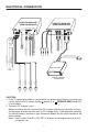
ELECTRICAL CONNECTION RADIO/TV MAIN UNIT (VIEW FROM REAR) RADIO/TV MAIN UNIT (VIEW FROM FRONT) TV DIVERSITY ANTENNA INPUT AV INPUT AV1 RADIO CONTROL CDC SET Rch RED GREY PLUG BLACK PLUG B BLACK CABLE TO SELECT CD CHANGER’S SORT VIDEO OUTPUT Lch WHITE 75ohm RF WIRE (BLACK) REAR RCA CABLE (FOR RCA LINE VERSION ONLY) FRONT RCA CABLE Lch WHITE Rch RED (GREY) (BROWN) RADIO ANTENNA INPUT TO CD CHANGER TV DIVERSITY ANTENNA INPUT TV CONTROL GREY/BLACK GREY CHOKE BOX BLACK GROUND YELLOW MEM
OPERATION LOCATION AND FUNCTION OF KEYS 6 1 11 12 14 7 8 13 5 4 17 18 19 15 20 4 10 8 3 21 16 9 2
OPERATION LOCATION AND FUNCTION OF KEYS 30 22 23 24 26 25 27 31 37 36 38 34 32 28 33 29 35 1. 2. 3. 4. 5. 6. 7. 8. 9. 10. 11. 12. 13. 14. 15. 16. 17. 18. 19. PWR MUT LCD T/F SEL VOL VOL RESET IR BND MOD TUNE/SKIP TUNE/SKIP M1 ~ M6 AS/PS CD + CD – RPT 20. 21. 22. 23. 24. 25. 26. 27. 28. 29. 30. 31. 32. 33. 34. 35. 36. 37. 38. 9 SCN RND TV/AV 0 ~ 9 Numeric Buttons -/-- Digital Selecting Button MUTE DSP (=SCREEN DISPLAY) SORT CH + CH – POWER (OPEN/CLOSE) VOL + VOL – ANGLE ADJ. + ANGLE ADJ.
OPERATION By pressing MOD button (12), you can select desired playing mode among TV, radio and CDC. GENERAL OPERATION • ON/OFF Switch on the unit by pressing PWR button (1). When system is on, press it again to turn it off. CAUTION: The unit cannot be switched into TV mode, when the car is running. So at this time, you just select playing mode between radio and CDC. • SELECTING SOUND MODE Press SEL button (6) to move display through volume, bass, treble, balance and fader functions.
OPERATION - Auto Memory Scanning Check the stations stored in the preset memories. Press to retrieve automatically the current stations stored in six preset memories and it will display for several seconds. Press either the AS/PS button (16) again or anyone of the memory buttons to stop the scan operation. During the preset scan operation, the channel number flashes on the display for several seconds. Preset station scan continuously in the pre-selected band.
OPERATION TV OPERATION OPEN/CLOSE Button (2) • REMOTE SENSOR On the screen display, there is a remote sensor IR (10) to receive remote control signal. You can point the remote control handset to IR (10) and press function keys on the handset to control TV. The unit is also connected an external remote receiver (See the electrical connection diagrams on Page 7 & 8), and the function is the same with IR (10). Fig. 1 - When the display stretches to a certain location, it will turn upward automatically.
OPERATION In this case, you also need to consider if the IR (10) is available. • PICTURE ADJUSTMENT/PROGRAM SETTING/SYSTEM CONTROL In TV mode, press MENU button (36) to enter the main menu. And the menu includes three sub-menus: PICTURE MENU, TUNER MENU and SYSTEM MENU. Press the button repeatedly or press / buttons (37) to select the desired item then press / buttons (38) to enter the corresponding sub-menu to set.
OPERATION • VOLUME ADJUSTMENT Press VOL + button (32) or VOL – button (33) to adjust volume level. • MUTE Press MUTE button (25) to mute the sound. Press the button again, the screen will display “VOLUME XXX” for about 4 seconds, and this is the AUDIO level setting value of the TV unit. The users may not mind it, and that adjust the volume level by VOL + (32) and VOL – (33) buttons.
SPECIFICATION GENERAL Power Supply Voltage Maximum Power Load Impedance Tone Controls - Bass (at 100 Hz) - Treble (at 10 KHz) : DC 12 Volts, Negative Ground : 4 x 60 Watts : 10 Ampere (max.) : + / – 10 dB : + / – 10 dB TV Monitor Screen Size Resolution TV Sensitivity : 6.4” TFT : 960 x 234 dots : 45 dBµV/PD (max.) @CH25 in average RADIO FM 87.5 to 107.
88-T1300-23