7" Wide LCD Monitor With 4 Mounting Options PLHR71 AU RM -1 0B PLVHR72 INSTRUCTION MANUAL www.pyleaudio.
Table of Contents About the liquid crystal display (LCD) panel 2 Troubleshooting guide 3 Precautions 3 Control & Layout for monitor / wireless remote 4 Accessories 5 Connection diagram 6 Replacing the remote control battery 6 Installing headrest with shroud 7-8 Installing sun-visor with shroud 9-10 installing of headrest case 11 Function setting 12-22 Specifications 23 1
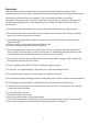
About the liquid crystal display (LCD) panel 1. Do not press on the LCD panel on the monitor unit as doing so can distort the picture or cause a malfunction, the picture may become unclear, or the LCD panel may be damaged. 2. Notes on cleaning -clean the LCD panel with a slightly damp soft cloth. - do not use solvents such benzine, thinner, commercially available cleaners or antistatic spray. 3. Do not use this unit temperatures under 5 oC (41 oF) or over 45 oC (113 oF). 4.
Precautions Please read this manual completely and carefully prior to attempt to install your new car video equipment. Install correctly, your new equipment will provide you with years of enjoyable and safe usage. Installing this unit requires technical expertise. This unit should be installed by a qualified technician or service personnel. If you try to install this unit by yourself, do it properly, referring to the installation and wiring diagrams in this operating manual.
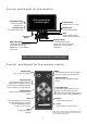
Control and layout for the monitor Front Audio Output Front audio output (headphones) Blue screen when no video signal Remote Sensor Remote control IR sensor Power On / Off Turn on/off the monitor Front A/V Input Front audio video input Menu Press to display MENU with functions and setting Power Cord (Male) Adjust Increase This multipurpose button serves to increase the selected parameters, such as volume, contrast etc.
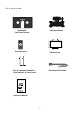
Accessories Universal Stand Headrest & Sun Visor Shroud AURM-10B Remote Control Headrest Case Key-for removing the monitor from headrest or visor shroud Extension Min Din Cable 7" Wide LCD Monitor With 3 Mounting Options PLHR71 AURM-10B PLVHR72 IN ST RU CT IO N MA NUAL www. pyl eau dio .
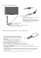
Connection Diagram 1 2 Fuse (2A) Fuse replacement Never use fuse with an amperage rating exceeding the one supplied with the unit as this could damage the unit. When replacing the fuse, be sure to use one that matches the amperage described on the original fuse. If the fuse blows, check the power connection and replace the fuse. If the fuse blows again after replacement, there may be an internal malfunction. In such a case, consult your nearest your’s dealer.
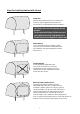
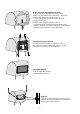
Steps For Installing Headrest with Shroud Setup work Remove the headrest and set it in an uncluttered work area. Pay the appropriate precautions to ensure that it is not damaged during the installation. CAUTION: make sure the screws are not long enough to go through the headrest! If you have any doubts about this type of installation, please consult your local mobile electronics retailer. Cutting and making holes in the headrest will cause electronic damage which is expensive to repair.
Route the cable through the headrest Run the supplied cable through the opening and out to the bottom of the headrest. If possible, conceal the wires with a shaft covering. Connect the power, ground and video leads to test the MONITOR. Before connecting the monitor, pull the connecting cable through the headrest shroud as shown in diagram. Place the headrest housing into the opening and secure with correct fasteners.
Steps For Installing Sun-visor with Shroud Setup work Remove the visor and set it in an uncluttered work area. Pay appropriate precautions to ensure that it is not damaged during the installation. CAUTION: make sure the screws are not long enough to go through the visor! If you have any doubts about this type of installation, please consult your local mobile electronics retailer. Cutting and making holes in the visor will cause electronic damage which is expensive to repair.
Route the cable through the visor Run the supplied cable through the opening and out to the bottom of the visor. If possible, conceal the wires using a shaft covering. Connect the power, ground and video leads to test the MONITOR. Before connecting the monitor, pull the connecting cable assembly through the visor housing as shown in diagram. Place sun-visor shroud into the opening and secure it with correct fasteners.
Rear side of headrest Front side of headrest 11
Function setting Press MENU button (1)from the remote or press manual button (1) from the monitor 2 to call out the function menu, press button (2 or 3) to the desired setting. 1 Video Signal Picture Parameters DDP OSD Setup Others 3 Remote OSD Monitor Press Menu button (1) to enter video signal input selection. The symbol show current video input. AV1 AV2 Return 2 1 SEL. MU ENT.
Video Signal Picture Parameters DDP OSD Setup Others OSD Press the button( 2or3) to adjust the symbol to choose “contrast. Press menu button (1) to enter contrast setting. Contrast Brightness Hue Saturation Gamma Function Scaling Return SEL. MU [Contrast: Narrows or widens the gap between black & white (darken & brighten)] 2 1 ADJ. EXIT RET 3 Monitor Remote Video Signal Picture Parameters DDP OSD Setup Others OSD Press button 2: adjust contrast to brighten level.
Video Signal Picture Parameters DDP OSD Setup Others OSD Press button 2: adjust brightness to lighter level. Press button 3: adjust brightness to darken level. Press button 1 to confirm setting. [Brightness adjustable level: 0~100 . Preset: 50] Brightness 50 2 1 -/+ MU EXIT SAVE / EXIT 3 Monitor Remote Video Signal Picture Parameters DDP OSD Setup Others OSD Press the button( 2or3) to adjust the symbol to choose “hue”. Press menu button (1) to enter hue setting.
Video Signal Picture Parameters DDP OSD Setup Others OSD Press the button( 2or3) to adjust the symbol to choose “letter box”. Press menu button (1) setup as letter box. The symbol show current selection. Scaling Full Screen Letter Box Paranoma Return [An image with an aspect ratio of 4:3 (regular picture)] 2 1 SEL. MU SET. EXIT RET 3 Monitor Remote Video Signal Picture Parameters DDP OSD Setup Others OSD Press the button( 2or3) to adjust the symbol to choose “paranromal”.
Video Signal Picture Parameters DDP OSD Setup Others OSD Press the button( 2or3) to adjust the symbol to choose “saturation”. Press menu button (1) to enter saturation setting. Contrast Brightness Hue Saturation Gamma Function Scaling Return SEL. MU [Makes color appear lighter or darker] 2 1 ADJ. EXIT RET 3 Monitor Remote Video Signal Picture Parameters DDP OSD Setup Others OSD Press button 2: makes colors appear darker. Press button 3: makes colors appear lighter.
Video Signal Picture Parameters DDP OSD Setup Others OSD Press button 2: appear 0 standard (preset). Press button 3: select 1(brighten) . Press button 1: to confirm setting. Gamma Function 0 2 1 -/+ MU EXIT SAVE / EXIT 3 Monitor Remote Video Signal Picture Parameters DDP OSD Setup Others OSD Press the button( 2or3) to adjust the symbol to desired setting (scaling). Press menu button (1) to enter scaling setting. Contrast Brightness Hue Saturation Gamma Function Scaling Return SEL.
Video Signal Picture Parameters DDP OSD Setup Others OSD Press the button( 2or3) to adjust the symbol to choose enable. Press menu button (1) setup as clearness picture. The symbol show current selection. Adjust the symbol to RETURN and press menu button (1) to exit. Enable Disable Return [Set enable as smartnous technology support] 2 12 SEL. MU ADJ.
Video Signal Picture Parameters DDP OSD Setup Others OSD Press the button( 2or3) to adjust the symbol to choose “language”. Press menu button (1) to enter language setting. Language Select OSD Timeout Transparency Information Memory Recall Return SEL. MU ADJ. [Setting On Screen Display language] 2 1 EXIT RET 3 Monitor Remote Video Signal Picture Parameters DDP OSD Setup Others OSD Press the button( 2or3) to adjust the symbol to desired language (English).
Video Signal Picture Parameters DDP OSD Setup Others OSD Press button 2: increase OSD timeout. Press button 3: reduce OSD timeout. Press button 1 to confirm setting. [Timout level: 10~60 . Preset:30 seconds] OSD Timeout 30 2 15 -/+ MU EXIT 1 SAVE / EXIT 3 Monitor Remote Video Signal Picture Parameters DDP OSD Setup Others OSD Press the button( 2or3) to adjust the symbol to choose “transparency” setting. Press menu button (1) to enter OSD transparency setting.
Video Signal Picture Parameters DDP OSD Setup Others OSD Press the button( 2or3) to adjust the symbol to choose “information”. Press menu button (1) to enter information. Language Select OSD Timeout Transparency Information Memory Recall Return SEL. MU [Appear video input information] 2 1 ADJ. EXIT RET 3 Monitor Remote Video Signal Picture Parameters DDP OSD Setup Others OSD Show video signal input information. Move the symbol to “RETURN” and press menu button (1) to exit.
Video Signal Picture Parameters DDP OSD Setup Others OSD Move the symbol to “RETURN” and press menu button (1) to exit. Exit VCOM Adjust Display Model: Rotate [Fully exit the setting] 2 1 SEL. MU ADJ. EXIT RET 3 Monitor Remote Video Signal Picture Parameters DDP OSD Setup Others OSD Adjust to the picture rotate Exit VCOM Adjust Display Model: Rotate 2 1 SEL. MU ADJ. EXIT RET 3 Monitor Remote Press button 2: set volume increase. Press button 3: set volume reduce.
Specifications: LCD Drive Method: a-SI TFT Active Matrix Visible Screen Size: 7 Inch Wide Screen (Diagonal) Aspect Ratio: 16:9 Display Format: 480 x RGB x 234 Number of Pixels: 336,960 Response Time: 15ms Backlight : High Brightness CCFT Luminance: 350 cd/m 2 #3 Backlight Life: 10,000 Hrs #1 Contrast Ratio: 300:1 Viewing Angle: (H/V): 120 o / 100 o Operation Temperature: -20 oC ~ 70 oC / -2 oF ~ 158 oF Video Color System Input: NTSC & PAL Compatible On Screen Display: English Rear Video Input Terminals: RCA