Aura Series (PP-5000 / PP-5200) Thermal Printer User's Guide Rev.: A0 IMPORTANT!!!! Please read carefully before using this printer Before opening the Top Hood, make sure there is no paper jam or cutter jam trouble. (Read page 3-4, 3-5 and Warranty Limit in the user’s Manual.
Federal Communications Commission Radio Frequency Interference Statement This equipment has been tested and found to comply with the limits for a Class A digital device, pursuant to Part 15 of the FCC Rules. These limits are designed to provide reasonable protection against harmful interference when the equipment is operated in a commercial environment.
Table Of Contents GETTING STARTED . . . . . . . . . . . . . . . . . . . . .1 CONGRATULATION . . . . . . . . . . . . . . . . . . . . . . 1 PRODUCT BRIEFING . . . . . . . . . . . . . . . . . . . . . 1 UNPACKING . . . . . . . . . . . . . . . . . . . . . . . . . . . . . 1 OPTIONS . . . . . . . . . . . . . . . . . . . . . . . . . . . . . . . . 1 MAIN PARTS ON THE EXTERIOR . . . . . . . . .1 INDICATORS . . . . . . . . . . . . . . . . . . . . . . . . . . . . 1 -- 1 -- 1 -- 1 -- 2 -- 3 -- 3 -- 4 QUICK START-UP .
Printing problems . . . . . . . . . . . . . . . . . . . . .3 Paper jam problems . . . . . . . . . . . . . . . . . . . 3 Auto cutter problems . . . . . . . . . . . . . . . . . . 3 Advanced analysis tool . . . . . . . . . . . . . . . . .3 -- 2 -- 4 -- 4 -- 6 SPECIFICATIONS . . . . . . . . . . . . . . . . . . . . . . . . . . . 4 -- 1 PRINTER . . . . . . . . . . . . . . . . . . . . . . . . . . . . . . . . 4 -- 1 PAPER . . . . . . . . . . . . . . . . . . . . . . . . . . . . . . . . . . .4 -- 1 POWER ADAPTOR .
I. GETTING STARTED A. CONGRATULATION You have made a very wise decision by purchasing the easy loading ; low noise ; high resolution ; light weight ; high reliability thermal printer Aura (PP-5000 & PP-5200) series of Posiflex products. This series of printers has been elegantly designed for a Point-Of-Sale, kitchen & kiosk application.
Aura series also supports user’s company’s LOGO downloading for superior performance. It even supports some enhancement capability for reminder function to persons around. It can be used to drive a separately purchased kitchen bell for such reminder function in noisy environment. This printer also supports application in different countries of various kinds of power systems by changing the power cord to the power adaptor.
ordered). b Power supply cable (when no power adaptor ordered) This printer power supply cable is used to supply power to the printer from the Posiflex POS system. … This User’s Manual D. OPTIONS • 38 mm paper roll adaptor (for PP-5000 only) • Kitchen bell (KL-200) • Language to add to standard model: Japanese Kanji; Korean; Traditional Chinese or Simplified Chinese, etc.. • Wall mount kit E.
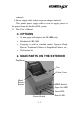
Front View Power Switch Rear View Serial Connector Power Connector Parallel Connector Peripheral Connector Bottom View Screws Window Plate Screw Setup Window F.
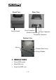
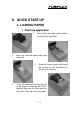
II. QUICK START-UP A. LOADING PAPER 1. Desk top application 1. Press down the hood release button to release the top hood. 2. Raise the released hood wide open manually. 3. 4. Drop the thermal paper roll inside the printer in the orientation as shown in the picture. Close the hood back leaving the tail of the paper roll coming out of the opening between the hood and the top cover. Tear off excessive paper.
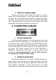
2. When to replace paper Whenever the printer gives paper out signal or a red line appears on the thermal paper, it is the proper timing for replacing the paper. Do not wait till the print engine is dragging the paper roll at the very end. Remove the leftover and replace a new paper roll as illustrated above to prevent excessive paper dust in the printer and consequently possibility for paper jam. B. CONNECTING CABLES 1.
keep parallel interface in fast operation, please adjust in setup window the switch positions both 1, and 2 to ON leaving the rest unchanged as factory default setting. 3. Peripheral connection The peripheral controller is a 6 pin RJ11 jack between the power connector and the parallel connector. With use of Posiflex cash drawer cable 20863018001 (CCBLA-180-1) come with cash drawer, this port can control a Posiflex cash drawer CR3100 or CR3200 or CR4000 or CR4100.
5. Power on When all the above cable connections are made correctly, you may connect your power adaptor to the wall outlet. Make sure that the type of power cord and the voltage requirement of the power adaptor meet the local power conditions. Now the printer is ready for power on. 6. Self test Press and hold down the feed button while turning the power switch on. The printer will then perform a self test. A sample slip of self test result is printed below.
The header is printed in text mode and the rest part of this slip is printed in page mode. If FEED button is pressed at this moment, a font table will be printed in text mode again. To exit the test printing, please turn the printer off and on again. C. SPECIAL ADJUSTMENTS 1. Paper near end sensor The near end Paper Roll Shaft Hold sensor for paper roll in the printer is able Sensor Block to have the printer work with paper rolls Sensor Position Adjust of several bobbin sizes.
either paper near end sense or paper feed action. It is also noticed that some market available paper roll has extremely light bobbin, easily causing the paper roll to go off position when paper feeding with low remaining paper. In this case, the paper near end sensor may function abnormally and it would be a good solution to set in the setup window to have the printer to send busy only when input buffer is full and not based on every off line signal. 3.
III. MAINTENANCE GUIDES A. MAINTENANCE GUIDE LINES • • • Always turn off and disconnect power before opening the hood or cover. The areas around the print head and motor become very hot during and just after printing. Do not touch them. When handling the interior of the thermal printer, please pay attention not to be hurt by any sharp edge of the metal parts. B. GENERAL CLEANING Please use soft hair brush or compressed air to clear away any dust or paper scraps accumulation inside the printer.
Before putting back the paper roll for printing, alcohol solvent must be dried completely. D. TROUBLE SHOOTING This section gives solutions to some printer problems you may have. 1. General Problems No LED lights up on control panel when switched on – Make sure that the power supply cables are correctly plugged into the printer, the power adaptor and to the power outlet. Make sure that power is supplied to the power outlet. If the outlet is controlled by a switch or timer, try use another outlet. 2.
If there is no paper jam and the print head is not overheated, turn off the printer and wait for half a minute then turn it back on. If the problem still remains, contact a qualified service person. Nothing can be printed with ERROR LED OFF – Try to run self-test according to previous chapter to check if the printer itself works properly. If the self-test passes, check the following: a. Check the connection of the interface cable at both the printer and computer ends.
setup and changing the switch positions 1 and 2 in the printer setup window to ON may help. 3. Paper Jam Problems Paper is jammed inside the printer – Turn off the printer and open the top hood by releasing the hood lock. Remove the jammed paper and reinstall the paper roll. Close the hood properly and firmly. Then turn on the printer for operation. If the auto cutter is jammed, the print hood will be locked.
cutter blade along the track and reset it to home position. Please test push the top hood release button from time to time to see if the hood opens as result of cutter position reset. Close the cutter cover back when done. Push down to test release Top Hood Use Phillips screw driver to reset cutter for PP-5000 back to home position For PP-5200 please refer to pictures below and lift up a transparent protective cover over the adjustment wheel.
Please use manual cutter as temporary alternative measure once the auto cutter malfunctioned. 5. Advanced Analysis Tool This printer supports Hexadecimal Dump for experienced user to view exactly what data is received by the printer. This can be useful in finding software problems. To start the dump mode: Turn off printer; Open print hood; Hold down FEED button while turning printer on; Close the hood. To stop the dump mode: Press the FEED button to print out the last line; Turn off the printer.
IV. SPECIFICATIONS A. PRINTER ITEM Printing method Effective printing width Thermal head configuration PP-5000 Printing speed PP-5200 Paper feed method Paper load method Auto-cutter type Auto-cutter capability Manual cutter Dot Pitch Input power type Input voltage Dimension (mm) Weight SPECIFICATION Thermal sensitive line dot method 54 mm 432 dots / line 120 mm /sec. 220 mm /sec. Friction auto-feed Drop and use Guillotine type Partial cut (1 point at center left) Saw tooth blade 0.125 x 0.
C. POWER ADAPTOR ITEM INPUT VOLTAGE INPUT FREQUENCY INPUT CURRENT OUTPUT VOLTAGE OUTPUT POWER STATIC LOAD OUTPUT REGULATION MTBF EMI STANDARDS REQUIREMENT 100 V AC ~ 250 V AC 50 ~ 60 HZ 1.5 A MAX. @ 115 V AC + 24 V DC 60 W 0 A ~ 2.
V. TECHNICAL INFORMATION A. INTERFACES 1. Peripheral interface The connector for peripheral control is a 6P6C RJ11 jack with the following pin assignment. The best recommended cash drawers to this connector are Posiflex CR3100, CR3200, CR4000 and CR4100. Using the cable 20863018001 (CCBLA-180-1) delivered with the cash drawer, the Aura series can control one dedicated cash drawer. However, by using an optional split cable 20867023800 (CCBLA-238), Aura series controls two cash drawers through this connector.
2. Serial interface The serial interface cable is a RJ45 plug to DB9F cable of length 1.8 meters (about 6 feet). To use the serial interface with a distance longer than the cable length can be achieved through use of LAN cable and a RJ45 jack to DB9F converter. Please insert one end of the LAN cable into the RJ45 jack of the printer and the other end into the RJ45 jack of the converter. Connect the DB9F end of the converter to the COM port of host system.
points to the connector area of the printer. The OFF direction points to the power switch. The functions of each position may evolve with the revisions of the firmware. The information below applies to the latest version to the date of print of this manual. This 8 position DIP switch works as following: Switch ON OFF position 1 RS232 baud rate definition or Parallel interface definition (ref.
For switch position 5, if the switch is set to ON, the busy signal is sent to host only when input buffer is full. When it is set to OFF, busy signal is sent to host whenever an off line status occurs. Therefore, signals including the paper near end detect will generate busy signal to the host. Consequently, the printing may be stopped even when there is still a long way to go before the paper roll is actually exhausted.
VI. USEFUL TIPS • Please note that only those qualified technicians may adjust several jumpers for some technical settings. Please visit our web site http://www.posiflex.com or http://www.posiflex.com.tw for details of the technical information such as driver installation, DIP switch settings and command sets etc. if required. • Place the printer on a sturdy, level surface. • Choose a place that is well ventilated and free of excessive dust, smoke or fume.
• Do not use a power outlet of a circuit shared with any equipment that uses a lot of power or causes great electrical noises, such as a copier, electric motors or a coffee maker. • Do not use thermal paper containing Sodium (Na+), Potassium (K+) and Chlorine (Cl-) ions that can harm the print head thermal elements. • If the surface of thermal paper is scratched with a hard object such as a nail, the paper may become discolored.