PP5600 SERIES POS PRINTER USER’S MANUAL Rev.: A Do not connect cables in ways other than those mentioned in this manual. Different connections may cause equipment damage and burning. Never attempt to repair this product yourself. Improper repair work can be dangerous.
Federal Communications Commission Radio Frequency Interference Statement This equipment has been tested and found to comply with the limits for a Class A digital device, pursuant to Part 15 of the FCC Rules. These limits are designed to provide reasonable protection against harmful interference when the equipment is operated in a commercial environment.
Table Of Contents BEFORE STARTED . . . . . . . . . . . . . . . . . . . . . . . 1 CONGRATULATION . . . . . . . . . . . . . . . . . . . . . .1 PRODUCT BRIEFING . . . . . . . . . . . . . . . . . . . . . 1 Descriptions . . . . . . . . . . . . . . . . . . . . . . . . . . 1 Features . . . . . . . . . . . . . . . . . . . . . . . . . . . . .1 MODELS . . . . . . . . . . . . . . . . . . . . . . . . . . . . . . . . .1 UNPACKING . . . . . . . . . . . . . . . . . . . . . . . . . . . . . 1 OPTIONS . . . . . . . . . . . .
Printing problems . . . . . . . . . . . . . . . . . . . . .3 -- 2 Paper jam problems . . . . . . . . . . . . . . . . . . . 3 -- 3 Auto cutter problems . . . . . . . . . . . . . . . . . . 3 -- 3 SPECIFICATIONS . . . . . . . . . . . . . . . . . . . . . . . . . . . 4 -- 1 PRINTER . . . . . . . . . . . . . . . . . . . . . . . . . . . . . . . . 4 PAPER . . . . . . . . . . . . . . . . . . . . . . . . . . . . . . . . . . .4 RIBBON CASSETTE . . . . . . . . . . . . . . . . . . . . . . 4 POWER ADAPTOR . . . . . . .
I. BEFORE STARTED A. CONGRATULATION You have made a very wise decision by purchasing the easy loading; high performance; high reliability 9 pin dot matrix impact printer Aura PP5600 series of Posiflex products. This series of printers has been elegantly designed for a Point-Of-Sale, kitchen & kiosk application.
It even supports some enhancement capability for reminder function to persons around. It can be used to drive a separately purchased kitchen bell for such reminder function in noisy environment. This printer also supports application in different countries of various kinds of power systems by changing the power cord to the power adaptor. The Aura PP 5600 series also supports an optional journal paper roll rewinder when non-carbon copy paper roll is used. 2.
• Supports Posiflex kitchen bell drive when used as kitchen printer • Hardware hand shaking in serial interface through DIP switch selection • Manual paper cut mechanism for PP5600D or guillotine type auto cutter plus manual cut mechanism for PP5600B • Supports ESC command • Dimension: 228 mm (l) x 158 mm (w) x 140 mm (h) C. MODELS PP5600D – with manual cutter PP5600B – with auto cutter PP5600A – with take up rewinder and auto cutter D.
Length of the interface cable depends on whether the order includes the power adaptor. When power adaptor is included, the interface cable is 6 ft long for stand alone application. When the power adaptor is not included in the order, the interface cable is a shorter one for integrated application in Posifle x POS system. … One of the power sources: a Power adaptor + power cord (depend on country type ordered).
F. IMPORTANT TIPS Place the printer on a sturdy, level surface. Choose a place that is well ventilated and free from direct sunshine and excessive heat, dust, smoke or fume. Never attempt to disassemble or modify this product. Unauthorized interior access voids product warranty. Do not connect a telephone line to the peripheral port. Otherwise, both printer and telephone line may be damaged. Do not touch the print head after printing. It can become very hot. Use a grounded AC power outlet.
G.
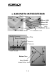
Interior View Auto Cutter Ribbon Cassette Area Paper Guide Roller Paper Roll Area Lift Tab Indicators • Power LED: green • Error LED: red • Paper Out LED: red 1-7
II. QUICK START-UP A. CONNECTING CABLES 1. Serial connection All the external connectors are in the recessed area at the rear bottom. The serial connector is a 9 pin D sub Female connector at the right in the picture above. Apply the male connector of RS232 cable to this port for serial application. Please note that when serial connection is used, there must be no cable connection at the parallel port on the printer.
split cable 20867023800 (CCBLA-238) is used instead, this port can control two cash drawers of above models. When the printer is used as a kitchen printer, please use this port for kitchen bell connection instead. 4. Power connection The power connector is a 3 pin jack between the peripheral connector and the parallel connector. Either a Posiflex supplied power adaptor or a printer power cable from a Posiflex POS system can be connected to this connector to supply power for this printer.
B. LOADING / REPLACING RIBBON CASSETTE • Turn off the power to the printer. • Lift the front end of the top cover to remove it. • Open the auto cutter by pulling the tab up if it is installed in the printer. Lift (PP5600B) Tab • Remove slack in the ribbon by Fastening turning the ribbon feed knob of the Knob ribbon cartridge counterclockwise. The ribbon must be properly tightened to be able to set in position in installation.
• Turn the knob counterclockwise to remove slack in ribbon for use. • Apply even force to close the auto cutter (PP5600B) so that the small lug of auto cutter Seat lug outside can seat in right position on the bracket below bracket of the print mechanism as in the picture. • Close the top cover by fitting its rear end lug first for ribbon replacement only or go on loadin g paper as in next paragraph. Î š C. LOADING PAPER 1.
3. paper feed roller inside the print mechanism then the paper will automatically advance to proper position (paper exit of print mechanism). In case there was a slip at the insertion of the leading end of paper roll and you want to keep same heading clearance, you may press the FEED button to advance the paper to position. Close the top cover back.
bottom of the slip is an indicator for adjustment on socalled bi-directional printing offset. E. SPECIAL ADJUSTMENTS 1. Paper near end sensor If the paper near end sensor is Fixing Screw installed in the printer and enabled, a fine tuning on the position of the paper near end sensor may be required for different outer diameter of the paper roll bobbin. Please refer to the picture at right from inside the Sensor Head paper roll compartment that there are a fixing screw and a sensor head in the wall.
position switch at the left is coded S2 for general printer settings. a.Bi-directional printing offset - S1 On Off On Off On Off On Off On Off On Off On Pos. 1 On Off Off On On Off Off On On Off Off On On Pos. 2 Off On On On On Off Off Off Off On On On On Pos. 3 Off Off Off Off Off On On On On On On On On Pos. 4 Value 0 1 2 3 4 5 6 7 8 9 10 11 12 13 14 15 The offset values in above table are in unit of half dot.
Positions 1 to 6 of the S2 switch define the communication protocol and handshaking criteria in RS232 interface. They shall always be set to positions 1 to 4 OFF with position 5 set to ON for parallel interface application. Position 7 of S2 alters the horizontal spacing between characters to get different print density on same font format. Position 8 of S2 determines whether to print only in one direction of print head operation or in both directions.
III. MAINTENANCE GUIDES A. MAINTENANCE GUIDE LINES Always turn off and disconnect power before start. Please pay attention not to be hurt by any sharp edge of the metal parts when handling the interior of the printer. Do not touch the print head and motor after printing. It can become very hot. Never use benzene, benzine, thinner, trichloroethylene alcohol, or ketone based solvents on the printer’s plastic and rubber components. B.
2. Printing Problems Nothing can be printed with ERROR LED ON – Check the Paper Out LED. If it is ON, most probably the paper roll is not installed or is at or near the end. Install a new paper roll. If the Paper Out LED is OFF, please check for paper jam described in next item. If there is no paper jam and the printer has been printing for quite a period of time, the print head may be overheated. It will usually cool back in few minutes and the printing will resume.
3. Paper Jam Problems Paper is jammed inside the printer – Please follow procedures below. Do not touch the print head and motor after printing. It can become very hot. • Turn off the printer. • Open the top cover after the print head cools down. • Cut the paper roll from the paper intake slot with a pair of scissors. • Open the auto cutter by pulling the tab up if it is installed in the printer. (PP5600B) • Turn the printer power back to on.
Auto Cutter Adjustment Window To check for home position of the auto cutter, please open the auto cutter and look into the blade slot and the spindle hole as in pictures below. Use proper tool to cut away the paper around auto cutter if it presents obstacle to the actions. Clear away any paper scraps from the auto cutter once it is reset to position.
IV. SPECIFICATIONS A. PRINTER ITEM Printing method Print head configuration Printing direction Effective printing width Printing speed (max.) Paper feed method Paper load method Manual cutter Auto-cutter capability Dot Pitch Paper feed pitch (min.) Paper feed holding force Paper feed speed (max.) Input power type Input voltage Power consumption Dimension (mm) Weight SPECIFICATION Dot matrix impact method 9 pins Bi-directional; logic seeking 59.85 mm 4.
C. RIBBON CASSETTE ITEM RECOMMENDED TYPE COLOR RIBBON MATERIAL RIBBON WIDTH CASSETTE DIMENSION EXPECTED LIFE REQUIREMENT RC200P Purple Nylon 66 13 mm 144.4 (W) x 65 (D) x 26.7 (H) mm 3 million characters D. POWER ADAPTOR ITEM INPUT VOLTAGE INPUT FREQUENCY INPUT CURRENT OUTPUT VOLTAGE OUTPUT POWER STATIC LOAD OUTPUT REGULATION VPP RIPPLE & NOISE MTBF EMI STANDARDS REQUIREMENT 100 V AC ~ 250 V AC 50 ~ 60 HZ 1.5 A MAX. @ 115 V AC + 24 V DC 52 W MAX. 0 A ~ 2.