DOLBY DIGITAL/DTS AV RECEIVER PT-690A R MASTER VOLUME DOLBY DIGITAL/DTS AV RECEIVER PT-690A POWER STATION ON MEMORY OFF - TUNING + STANDBY MUTE WOOFER ON/OFF DIMMER DIGITAL IN SURROUND MODE STEREO PROLOGIC DTS/ DOLBY DIGITAL OPTICAL S-VIDEO AV3 IN PHONES High Per f ormance DSP Digit al Pr ocessing VIDEO L AUDIO R INPUT SELECTOR
CONTENTS Important Safety Instruction…………………………………………………………………………………………2-3 Before Use………………………………………………………………………………………………………………..4 Connection……………………………………………………………………………………………………………..5-9 Antenna Connection…………………………………………………………………………………………………..5 Standard speaker setup for surround sound………………………………………………………………………...6 Speaker connection……………………………………………………………………………………………………7 DVD player, Television (Monitor), etc. connection………………………………………………………………..8-9 Remote control unit……………………………………………………………………………………….
IMPORTANT SAFETY INSTRUCTION CAUTION: READ THIS BEFORE OPERATING YOUR UNIT. 1. READ AND FOLLOW INSTRUCTIONS---All the safety and operation instructions should be read before the product is operated. Follow all operation instructions. 2. RETAIN INSTRUCTIONS---The safety and operation instructions should be retained for future reference. 3. HEED WARNINGS---Comply with all warnings on the product and in the operation instructions. 4. CLEANING---Unplug this product from the wall outlet before cleaning.
IMPORTANT SAFETY INSTRUCTION 12. CONTACT THE SERVICE DEPARTMENT SHOULD THE BELOW CONDITIONS EXIST— a. When the power-supply cord or plug is damaged. b. If liquid has been spilled, or objects have fallen into the product. c. If the product has been exposed to rain or water. d. If the product does not operate normally after following the operation instructions, adjust only those controls that are covered by the operation instructions. e. If the product has been dropped or damaged in any way. f.
BEFORE USE READ THIS BEFORE OPERATION 1. Choose the installation location of your unit carefully. Avoid placing it in direct sunlight or close to a source of heat. Also avoid locations subject to vibration and excessive dust, cold or moisture. 2. The ventilation holes should not be covered. Make sure there is enough space above and beside the amplifier/receiver (about 4 inches). Do not place a CD player or other equipment on top of the amplifier/receiver. 3.
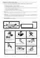
CONNECTION Wrap the core conductor around the central metal fixture as shown. Crimp the jagged metal fixtures so they hold the braided portion using pliers, etc. Put the cover back in place. FM INDOOR ANTENNA If you live reasonably close to a transmitter and want to use the provided lead-type FM antenna, you will have to connect it direct to the “FM 75Ω” socket.
CONNECTION Standard speaker setup for surround sound 1 2 3 4 6 5 7 8 1. TV or Screen 4. Center Speaker 7. Surround Right Speaker 2. Front Left Speaker 5. Front Right Speaker 8. Listening Position 3. Subwoofer 6. Surround Left Speaker Standard speaker setup for surround sound ● Front right and left speakers ● Center speaker Produces a rich sound image by serving as a sound source for the front right and left speakers and enhancing the sonic movement.
CONNECTION SPEAKER CONNECTION RS LS L RS SUB LINE OUT CENTER LS RIGHT LEFT SPEAKERS 8 SPEAKERS 8 CENT ER FRONT SUBWOOFER FRONT R L Power cord (AC) Be sure to connect the power cord to an AC outlet, which supplies the correct voltage. Hold the power plug when plugging or unplugging the power cord. SUBWOOFER LINE OUT Use this jack to connect an active subwoofer.
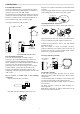
CONNECTION DVD PLAYER, TELEVISION (MONITOR), ETC. DVD,VCD VIDEO OUT AUDIO OUT R VIDEO IN S-VIDEO OUT DIGITAL OUT L S-VIDEO IN MONITOR(TV) When connecting video components such as DVD players, cable boxes, satellite receivers and television, you can use different types of cables depending on how the video component is equipped. monitor using just one video input on the TV (S-Video or RCA).
CONNECTION using a coaxial digital cable, leave the protection caps in both the video component and your Receiver. Audio connections: Some video components are equipped with special digital audio outputs (i.e. DVD players). If your video component is equipped with a digital audio output, it is recommended that you connect to the your Receiver using a digital cable. Digital audio cables are required to use the DTS and Dolby Digital surround sound modes.
REMOTE CONTROL UNIT BATTERY INSTALLATION By using the provided remote control unit, the receiver can be controlled from your listening position. To use the remote control unit, point it at the REMOTE SENSOR window of the receiver. Notes: Even if the remote control unit is operated within the effective range, remote control operation may not work if there are any obstacles between the unit and the remote control.
FRONT PANEL INFORMATION 1 2 3 4 5 8 6 7 9 STATION M EM ORY MASTER VOLUME DOLBY DIGITAL/DTS AV RECEIVER PT-690A POWER ON OFF STANDBY M UT E WOOFER ON/ OFF DIM M ER DIGITA L IN SU RROU ND M ODE STER EO PROLOGIC DTS / DOLBY DIGITAL OPTIC AL S-VIDEO VIDEO L A UDIO R INPUT SELECTOR AV3 IN PHONES 10 NO. & NAME 1. POWER 2. STANDBY INDICATOR 3. STANDBY 4. VFD DISPLAY UNIT 5. MASTER VOLUME 6. STATION 7.
REMOTE CONTROL INFORMATION 2 3 5 1 POWER 4 6 MUTE DELAY TIME SURROUND MODE BASS SPK SETUP 26 MEMORY DOLBY PL II 25 TREBLE 7 9 10 12 28 27 INPUT SUBWOOFER ON/OFF SELECT 8 29 STATION 11 DOLBY DIGITAL DIMMER CH SELECT DYNAMIC INPUT MODE TEST TONE BAND TUNING AUTO/ MANUAL LFE TRIM 24 23 21 22 20 19 18 TUNING 13 14 VOLUME ST/MONO 17 16 P T-6 9 0 A 12 15
REMOTE CONTROL FUNCTION NO. & NAME 1. POWER 2. MUTE 3. SURROUND MODE 4. DISPLAY 5. PRO LOGIC II 6. MEMORY 7. APS (without RDS) / PTY SEARCH (with RDS) 8. STEREO 9. DOLBY DIGITAL 10. STATION +/11. DYNAMIC 12. BAND 13. TUNING 14. AUTO MANUAL 15. TUNING + DESCRIPTION Push this button to turn the unit into standby mode, push it again to turn off the unit. Press this button to mute the sound, push again to cancel the mute function.
REAR PANEL INFORMATION 2 1 DVD IN VI DEO 1 IN 3 VI DEO 2 IN 4 VI DEO OUT DVD-S IN 5 6 7 8 9 VIDEO 1-S IN VIDEO-S OUT M an u fa ctur ed u n de r lice n se fr om Dig ita l T he a te r System s,In c.US Pa t.No .5,4 5 1,9 42 , 5 ,9 5 6,6 74 , 5 ,9 7 4,3 80 , 5 ,9 7 8,7 6 2 a n d oth er wo rld -wid e pa ten ts issue d a nd p en d ing ."DTS "a n d "DT S Dig ital S ur ro u nd " a re r eg iste r ed tra d em a rks o f Digita l Th ea ter Syste ms, Inc.
BASIC OPERATION BASIC OPERATION 1 BASIC OPERATION 2 P OWER A POWER & STANDBY/ON button Press this button to turn the power on. Press it again to turn the system off (power standby mode). The STANDBY indicator lights up in power standby mode and goes out when this unit is turned on.
BASIC OPERATION THE RADIO OPERATIONS Preset tuning MASTER VOLUME DOLBY DIGITAL/DTS AV RECEIVER PT-690A This facility is used to store FM, AM broadcasting from channel 1 to15 respectively. POWER ON OFF STANDBY M U TE W O O FE R O N / O FF D IM M ER D IG IT A L IN S U R RO U N D MODE S T ER E O P R O L O G IC D TS / D O L B Y D IG IT AL INPUT SELECTOR O P T IC A L S -VI D EO VID EO L A U D IO R AV3 IN Automatic Memory Presetting 1.
RADIO DATA SYSTEM (OPTIONAL) d) RT (Radiotext) RADIO DATA SYSTEM (RDS) RDS is a method for the transmission of additional information from local Radio Stations. It can only operated in FM mode. For example, name of the station broadcasting, name of the program or the type of program will be shown on the multi-function display. Press “DISPLAY” on remote control until “RT” appears. Some Text messages will be shown.
VIDEO OPERATIONS Playing Video sources MAST ER VOLUME DOLBY DIGITAL/DTS AV RECEIVER PT-690A PO WER ON OF F STANDBY MUTE WOOFER ON/OFF DIMMER DIGITAL IN SURROUND MODE STEREO PROLOGIC DTS/ DOLBY DIGITAL OPTICAL S-VIDEO VIDEO L AUDIO R INPUT SELECT OR AV3 IN PHONES 1. Select the DVD, VIDEO 1, VIDEO 2 or VIDEO 3 modes by rotating the INPUT SELECTOR or pressing the INPUT SELECT on remote control. 2. Play the component corresponding to the INPUT selected. 3.
DELAY TIME & DYNAMIC RANGE CONTROL DELAY TIME DYNAMIC RANGE CONTROL The delay time can be individually set for the Dolby Digital/Dolby Pro Logic II modes using the DELAY (CENTER/REAR) buttons. When you adjust the delay time in the Dolby Digital mode, an additional 15 ms is automatically added to the surround channels in the Dolby Pro Logic mode. The current setting is shown on the display. This button controls the compression range of sound track.
TEST TONE, LFE TRIMMER AND CHANNEL SELECT. TEST TONE Speaker Level balance Adjustment The test tone function is useful to adjust the relative volume between speakers in DOLBY DIGITAL or DOLBY PRO LOGIC II mode. Once the balance is set, you don’t have to change the balance as long as the speakers aren’t moved. 1. Adjust the MASTER VOLUME to the normal listening level. (Half of max. Volume is recommended) 2. Press the TEST TONE button (on the remote control) in DTS, Dolby Digital or Dolby PRO LOGIC II mode.
TROUBLESHOOTING To determine any problem with your receiver, always check the most obvious possible causes first. If any problem still remains after your having checked the items below, consult your nearest dealer. Problem Probable Cause Suggestion Amplifier When listening to the music in stereo. Speakers are connected wrong. After checking, if needed, reconnect. Left/right speakers reversed. Low hum or buzz sound Power cords or lighting placed near Place this product as far as possible this product.
SPECIFICATIONS AUDIO SECTION Audio Power Output Output Impedance Total Harmonic Distortion LINE INPUT Input Sensitivity/Impedance Frequency Response Tone Control Range FRONT (L/R) CENTER SURR. (L/R) FRONT (L/R) CENTER SURR. (L/R) Less than 0.05% Signal-Noise Ratio 300mV/47kΩ 20Hz~23KHz +0.5/-1dB BASS ± 6dB TREBLE ± 6dB 75dB WOOFER OUTPUT Rated Output/Impedance Frequency Response 500mV/10kΩ 10Hz~300Hz +3dB FM TUNER SECTION Frequency Range Sensitivity Antenna Terminal 87.