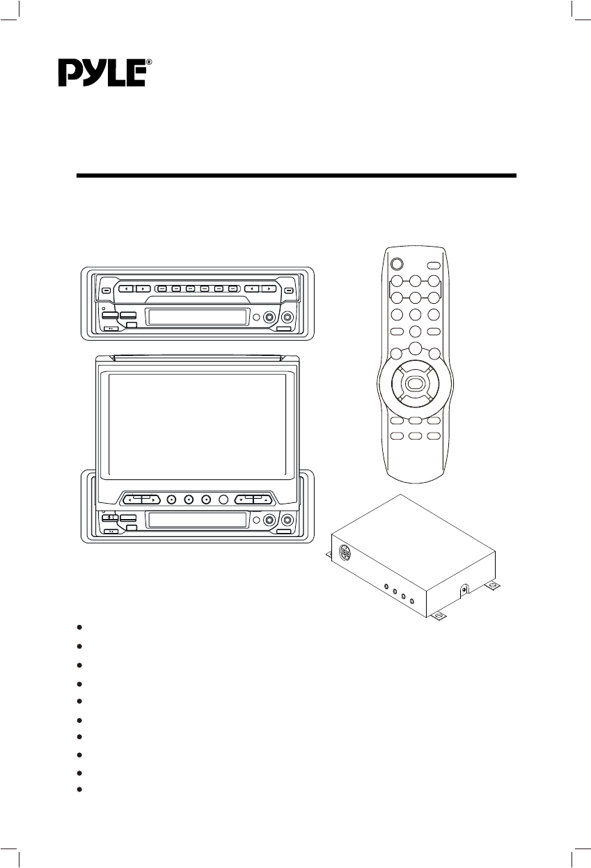
PLTV65R OWNER'S MANUAL Mobile Audio/Video System AM/FM/MPX/TV-Tuner PLL Synthesizer Stereo Radio Built In Amplifier Vertical Adjustable And Horizontal Rotatable Panel Automatically Memory Storing TFT Monitor Remote Control Optional TV Tuner (Separate Box) CD Changer Control 4 x 40 Watts www.pyleaudio.
CONTENTS Important Safety Instruction 3 Installation 4 DIN Front-Mount (Method A) 4 4 Installing the unit Removing the unit DIN Rear-Mount (Method B) 5 6 Wiring Connection Operation 7 8 Location and function of keys Switching on/off the unit Automatic memory storing& program scanning Local/distant Mono/stereo Scan CDC operation Switching to CDC mode Selecting tracks Pausing playing Previewing all tracks Repeating the same track Playing all tracks in random Selecting disc Operating when the monito
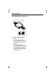
IMPORTANT SAFETY INSTRUCTION CAUTION: Please read and observe all warnings and instructions given in this owner's manual. Keep these instructions. Retain this booklet for future reference. Please read the following safety instructions carefully. 1.This set has been designed and manufactured to assure personal safety. Improper use can result in electric shock or fire hazard. The safeguards incorporated in this unit protect you if you observe the following procedures for installation, use and servicing.
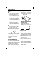
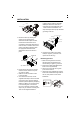
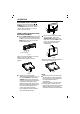
INSTALLATION TAKE OUT SCREW BEFORE INSTALLATION Notes: Choose the mounting location where the unit will not interfere with the normal driving function of the driver. Before finally installing the unit, connect the wiring temporarily and make sure it is all connected up properly and the unit and the system work properly. Use only the parts included with the unit to ensure proper installation. The use of unauthorized parts can cause Malfunctions.
INSTALLATION (Tapping Screw (5x25mm) and Plain Washer) to attach the other end of metal strap to a solid metal part of the vehicle under the dashboard. This strap also helps ensure proper electrical grounding of the unit. Sleeve L Key Outer Trim Ring R Key Spring Washer Hex Nut Metal Strap 5. Mount the sleeve by inserting the sleeve into the opening of the dashboard and bend open the tabs located around the sleeve with a screwdriver.
INSTALLATION DIN REAR-MOUNT (Method B) 3 1 2 4 5 1. 2. 3. 4. 5. Factory radio mounting bracket Car radio mounting bracket Screw After aligning the car radio mounting bracket with the factory radio mounting bracket, tighten the screws (5x5mm) at 2 places on each side. When fix the factory radio mounting bracket with the screws, use s standard-tipped screwdriver to open the tabs of the car radio mounting bracket to make them fit into theholes in the factory radio mounting bracket.
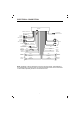
ELECTRICAL CONNECTION MAIN UNIT ANTENNA CONNECTOR Rch RED Lch WHITE VIDEO YELLOW Rch RED Lch WHITE VIDEO YELLOW (BLACK) CD CHANGER CONNECTOR SOCKET AV2 IN (RED) (GREY) AV OUT (GREEN) R.G.B.
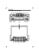
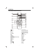
OPERATION LOCATION AND FUNCTION OF KEYS 9 1 7 8 6 2 16 28 29 30 15 31 12 32 33 14 10 4 Fig.A 5 23 22 19 20 21 Fig.
OPERATION LOCATION AND FUNCTION OF KEYS 34 35 37 36 38 40 39 41 42 43 44 46 45 47 49 48 51 52 53 50 / 1. 2. OPEN/CLOSE 3. MUTE 4. LCD 5. TFT Monitor 6. SEL 7. VOLUME 8. VOLUME 9. Reset 10. IR 11. BND 12. MODE 13. TUNING TUNING/TRACK (For CDC Version Only) 14. TUNING TUNING/TRACK (For CDC Version Only) 15. M1~M6 16. MO/ST 17. AUDIO 1 IN 18. VIDEO 1 IN 19. MENU 20. DSP 21. TV/AV 22. VOLUME 23. VOLUME 24. CHANNEL 25. CHANNEL 26. IR 27. 4:3/16:9 Selector 28. PAU(For CDC Version Only) 29.
OPERATION SWITCHING ON/OFF THE UNIT Switch on the unit by pressing / POWER button (1) on the front panel or POWER button (34) on the remote control. When system is on, press it again to turn the unit off. OPEN/CLOSE THE MONITOR AND ANGLE ADJUSTMENT Press OPEN/CLOSE button (2) on the front panel or point the remote control to IR (10) on the front panel and press OPEN button (35), the monitor will stretch automatically. Fig.
OPERATION REMOTE SENSOR There is a remote sensor IR (10) on the front panel. On the monitor, there is another remote sensor IR (26) to receive remote control signal. You can point the remote control handset to IR (10) (when the monitor doesn't stretch out) or IR (26) (when the monitor stretches out) and press function keys on the remote control to control the TV unit.
OPERATION Adjusting the loud In loud mode, use VOLUME / buttons (7&8) or VOL / buttons(47) to switch between loud on and off. When LOUD on, "LOUD" will show on the display (4). Directly press LOUD button (52) to reinforce the bass output. Press it again to release the function. Adjusting the equalization In equalization mode, use VOLUME / buttons (7&8) or VOL / buttons (47) to switch between the following mode and the corresponding information appears on the LCD (4).
OPERATION - signal and keep on each station for several seconds. At this time, press any one of the buttons (15) on the front panel or (37) on remote control, the current scanned station will be stored into the corresponding number button, then it keeps on scanning other stations. Retrieve a Preset Station Press any one of the buttons (15) on the front panel or (37) on remote control to retrieve a station which had been stored in the memory in advance the chosen number is shown on display.
OPERATION Press MO/ST button (16) on the front panel or ST/MO button (53) on remote control to select "MONO" or "STEREO". OPERATING WHEN THE MONITOR STRETCHING OUT When the monitor stretches out, the front panel of the unit is in state B (see Fig.B), you can operate the unit by using the current menu displayed on the 6.5 inch color TFT display (5).
OPERATION Then you can press VOL / buttons (48) to select hour or minute and press TUN/CH / buttons (47) to change the corresponding item. Menu Control operation in CDC mode Press MODE button (12) on front panel or MODE button (43) to select CDC mode. The following information will appear on the display (5).
OPERATION display, you can press "1 "button then press "6" button to select 16 channel. Menu control operation In TV mode: Press MENU button (19) or (45). The menu will show on the display (5). Volume adjustment Press VOLUME / buttons (23&22) or VOL / buttons (47) to adjust volume level. Screen display Press DSP button (20) on the front panel or DISP button (44) on remote control to display the current status such as TVch /AV1/AV2. Press DSP button (20) or DISP button (44) again to show the current time.
SPECIFICATION GENERAL Power Supply Requirements Maximum Output Power Current Drain : DC 12 Volts, Negative Ground : 4x40 watts : 15 Ampere (max.) TV Monitor Screen Size Resolution TV Sensitivity : 6.5" TFT : 1440 x 234 dots : 45dB V @CH25 in average RADIO Frequency Coverage Sensitivity (S/N=30dB) Image Rejection Stereo Separation FM 87.5 to 107.
MOBILE TV TUNER UNIT 18
CONTROL & FUNCTION KEYS 1 3 2 This unit can't be used separately and it must be used with other special system with the 13 -pin cable. The unit is connected to another system through the 13-pin din socket (3). And the unit can receive TV signal through the antenna input jack (2). 1 POWER INDICATOR LIGHT When the unit is connected to the other system with the 13-pin din cable and the other system turns on, the power indicator light (1) will be illuminated red and the unit turns on.
www.pyleaudio.