of connected operating OUI'erIPC terminal The list of package ....:;;.;;,..:..:...:..:...:..:...;;,.._ _.3. / Parts of receiver ) ~ }--- Probe Signal indicator ,, Inching bUllon FlJnction sWltchover """",, -~ DIP switch Testing indicator Wire sequence indicator RJ11 socket RJ45 !lOCket - - - - - SpoWght switch ( ~.
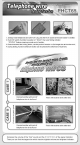
1. Directly insen telephone wire wtth RJll pkJg Into the RJ11 socket of the wire tracker·s emittl!(; 2. Push DIP switch 01 emitter to j)Os~ion of ' SCAN ' then wire lirKling Indicator "STAruS " ~ashes meaning r"KlIlllal work 01 emitter; 3. Press downward the inching Dutton . use the probe of receiver to find target wire at the other end ; 4. During testing .
1. Dire<:Uy insef! netwOO'k "";re "";th R.J45 plug Into the RJ45 socket of the wire tracker's emiHer, 2. Push DIP switch of emitter to pos~Kln of · SCAN" then wire fi nding ind icator " STATUS · flashes meaning normal work of emitter; 3. Press downward the inch" g button, use the ~ 01 receiver to find t"'llet wire at the other ..oo; 4.
Directly insert telephone wire with crecocile cla mp and RJll plug into th e RJl l socket of the wire tracker' s emitter: 2 Push DIP sw~ch of em itter to position of • SCAN " then wire finding ind ica tor " STATUS · flashes mean ing normal wark af emiller: 3. Press dawnward th e inchIng button , use the prabe al rece iver to l ind target wire at the ather end : 4. Dur ing testing, lunctkm switchaver button can be pressed lor switc hover of dual-t ane .
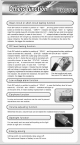
.......... ........................ ..................... . ............ ,'no..... ' VI',,,·•"e='i555=::::::5::5:::=5Netwo-.'; Collation • . .. .••••• _...- funetlOri. •• ••• I _ :.81.____ . _. ,....... ~._._.. ~... • •••• __ • • •~ Insert RJ45 plug at two ends of th e networ~ wire into the correspond ing sockets at emitter and rece iver 2 Push function sw~c h o ve rb utton on emitter to the pos~k>n 01 " TEST ' testing indical(\( · VER IFY " Ilashe s meaning normal wor~ 01 emrtter , 3.
Open circuit or short circui t testing function Push DIP switch on emitter to posilion 01 "TEST ' , and long press function sw~chover button on em~ te r for 2 seconds, • VERIFY ' ind icator will change "flash " to ' Iighting" insert the crystal plug wilh crocodile clamp into RJII, clamp the two ends 10 be tested with crocodile clamps, in case 01 short Circuit.
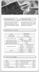
( \I Applicable users: ) Applicable scope : Te lecom post bure au/n et barllelecom en gineering companies I netw ork engineering companiesJpower supply/ army and other departmen ts requ iring wire, Wire engine eri ng or te lecom network and regular maintenance work: network line engineering 01 computer; oth er wire eng in eering and ma int enance_ CSpecification of product ) Sp ec ifica ti o n Ite m Product name Wire trac ker Power supply DC. 9V batt ery The max wo rking current Emitt e r ..