PLD10BT Motorized Foldout Monitor Holder 10.
To ensure safety while driving and to comply with laws, drivers should not watch video or operate the video device while driving.
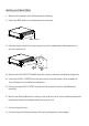
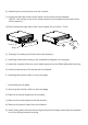
INSTALLATION STEPS 1.
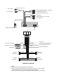
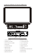
REAR AUDIO OUTPUT RCH RED REAR CAMERA INPUT YELLOW SUBWOOFER GREY VIDEO INPUT YELLOW LCH WHITE FRONT A/V OUTPUT RCH RED VIDEO OUTPUT YELLOW LCH WHITE RADIO ANTENNA JACK ISO CONNECTOR PINK IGNITION SWITCH(B+) MEMORY BACK-UP(B+) RED BROWN YELLOW GROUND(B-) BLUE BLACK FRONT LCH SPK. REAR LCH SPK. CHOKE BOX WHITE GREY WHITE/BLACK GREY/BLACK GREEN GREEN/BLACK VIOLET VIOLET/BLACK (B+)12V REAR CAMERA SWITCH (B-)PARKING BRAKE AUTO ANTENNA FRONT RCH SPK. REAR RCH SPK. WIRING DIAGRAM NOTE: 1.
2) Attaching the control panel onto the chassis; (1) Insert the left side of the control panel into the hollow of the chassis . (NOTE : the “bulge” point on the control panel must be attached into the hollow of the chassis .) (2) Gently push the right side of the control panel till you feel a “ Click” . Hollow 1 Bulge 2 3) Testing it for making sure that it can work properly . 4.
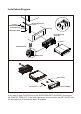
Installation Diagram DASH BOARD HEX NUT SPRING WASHER METAL MOUNTING STRAP PLAIN WASHER CONSOLE TAPPING SCREW SLIDE BRACKET HOUSING HEX BOLT SCREWDRIVER TABS KEY PLATE KEY PLATE PLASTIC FRAME If you want to take CHASSIS out of the SLIDE BRACKET HOUSING, first remove the PLASTIC TRIM OUT of the both sides away, then insert the two KEY PLATE into left and right side of chassis as above illustration.
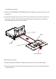
Installing the monitor. 1) Press the OPEN/MONITOR-ANGLE button to slide the monitor holder out and stand it up. 2) Insert the 2 bulges of the monitor into the 2 hollows of the monitor holder and flip up the monitor, then push the top middle part of the monitor to make the monitor attach onto the monitor holder. Hollow Bulge Hollow Bulge MONITOR REL Removing the monitor.
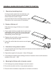
GENERAL KNOWLEDGE ABOUT REMOTE CONTROL 1. Removing insulating sheet If using remote control for the first time, you can see an insulating sheet at the bottom side of remote control as right. you must remove the insulating sheet as right. Otherwise, the remote control is disabled. 2. Replace lithium cell If the electric energy of lithium cell is weak, replace it.
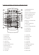
Locations and Names of Controls on Main Unit 16 4 12 10 9 18 11 13 3 17 8 5 7 15 2 1 Control Panel 14 6 Sliding Plate diagram after remo ving Control Panel 1. AUX IN JACK(A/V) 10. MUTE/PTY BUTTON 2. USB PORT and COVER 11. |<|| or CH1-6 BUTTON 4. REL BUTTON 13. >>|/CALL BUTTON 5. IR SENSOR WINDOW 14. SD/MMC CARD SLOT 6. RESET BUTTON 15. LCD SREEN 7. EJECT BUTTON 16. OPEN/MONITOR-ANGLE BUTTON 8. POWER/MODE BUTTON 17. MICROPHONE 9.
Locations and Names of Controls on Remote Control 1 2 3 5 7 9 11 13 15 MUTE MODE PLAY/PAUSE 20 STOP MO/ST ZOOM 4 6 23 PAIR LOUD MENU EQ CLK LO/DX 8 10 25 27 OSD BAND 29 ENTER TITLE/PBC 12 2. MUTE BUTTON 21 REDIAL 31 A/PS 22 3. HANG UP or REDIAL BUTTON 4. MONITOR-ANGLE BUTTON 24 26 28 30 37 5. CALL or PAIR BUTTON 6. MENU or SW BUTTON 7. >> BUTTON 8. SUBTITLE or LO/DX BUTTON VOL TOP RPT INT 1 2 3 32 VOL RDM 6 33 10. BAND or OSD BUTTON 35 11.
Same functions in any work source mode 1. POWER button and icon In power off mode, pressing POWER button on remote control or pressing POWER button on control panel powers on main unit. In power on mode, long pressing POWER button on control panel or on remote control or touch icon on source menu powers off main unit. 2. VOL knob & VOL+/VOL- buttons To adjust volume level, rotate VOL knob on control panel or press or hold VOL+ or VOL- button on remote control. 3.
The source menu displays as follows: Source Menu In source menu, touch one icon of DISC, RADIO, BT MUSIC, AUX, USB and SD Card to enter one work source of DISC, RADIO, BT MUSIC, AUX IN, USB and SD Card. 11.
In the SOUND page of SETUP menu, repeatedly touch the or icon to highlight one setting item of TREBLE, BASS, BALANCE, FADE, SUBWOOFER, LOUDNESS, RADIO LOC/DX(entering Source Menu in radio mode), RADIO STEREO(entering Source Menu in radio mode) and BUZZER ON/OFF. After highlighting a desired setting item, touch the or icon to set it.
Radio Operation 1. To enter RADIO mode(MODE button or RADIO icon) When you use MODE button or source menu (tapping RADIO icon) to enter RADIO mode, it will display radio interface as follows: FM1 88.50 90.00 98.00 * 87.50 MHZ 106.00 103.00 80.50 Some icons on radio interface correspond with the buttons on remote control or control panel as follows: icon = MUTE button - and + icons = VOL- and VOL+ buttons = VOL knob EQ icon = EQ button : To enter source menu.
5. To preset and listen to a memory station(1~6 icons or 1~6 buttons or CH1-6 button ) 1) Long touching one of 6 number(1~6) icons or long pressing one of 6 number(1~6) buttons can preset the current broadcasting station of the current band in the number memory bank; . 2) Briefly touching one of 6 number(1~6) icons or briefly pressing one of 6 number(1~6) buttons can listen to the memory station in the current band preset in the number memory bank.
It switches over to the AF for a short time, and the AF icon is light on screen(not flash). * In FM mode, when switching on AF mode, the radio auto searches for or preset only those RDS stations. * In FM mode, when switching on AF and TA modes, the radio auto searches for only those RDS stations broadcasting traffic announcement. 10. REGION mode use the RDS page of the SETUP MENU or the SEL and VOL buttons to set REGION mode on or off.
BT Operation 1. Pairing and Connecting Prior to using the BT device named BC_HF_V01 as a handfree system for a BTenabled mobile phone for the first time, you must pair and connect them as follows: * Prior to pairing and connecting, when displaying No Video interface of radio, CD, AUX IN or BT music, the logo BT flashes in the touch screen.
b. Use the number icons or buttons to input your desired phone number; * When inputting a wrong digit, use icon or < button to delete it. c. After finishing inputting, touch icon or press button on remote control to dial out. button on control panel or press 2) Redial last dialed phone number Touch icon or long press button on remote control to dial out the last dialed phone number. 3) Answer a call During ringing, the incoming telephone number displays in the the BT PHONE interface.
- and + icons = VOL- and VOL+ buttons = VOL knob icon = MUTE button EQ icon = short pressing EQ/LOUD button icon : Popping up BT PHONE interface(after pairing and connecting a mobile phone with BT function). icon = icon = and button button icons = and button icon: To enter source menu. TA icon : To switch TA mode on or off. AF icon : To switch AF mode on or off.
Disc/USB/Card Operation 1. Loading or unloading a disc, USB or card 1.1 Loading a disc, USB or card To play files in a disc, insert a disc with label surface up into disc slot. it will automatically play. * CAUTION OF USING DISC Label surface up 1) Handle a disc by its edge, do not touch the surface of play side. 2) Before inserting disc, wipe the disc outwards from the disc center with a clean, soft, dry, lint-free cloth. Do not use solvents /thinner such as petrol/benzine, cleaner.
1.2 Unloading a disc, USB or card To unload the disc in disc slot, use STOP button to stop playback and then press button on control panel or touch icon on source menu to eject disc, then remove it. To pull away the USB storage, use STOP button to stop playback, then you can remove the USB storage.
The Function Icons-boards display as follows: Function Icons-board 1 Function Icons-board 2 * Some icons on the Function Icons-boards descript as follows: : Same as MUTE button. : Same as VOL- button or rotating VOL knob with anti-clock wise. : Same as EQ button. CLK : Same as CLK button. LOUD: Same as long pressing EQ button. : Same as VOL+ button or rotating VOL knob with clock wise. SWF : Same as SW button. : Poping up source Menu. : Poping up Function Icons-board 1.
3. Function of controls on the touch screen/main unit/remote control 1. icon or button During playback, use it to pause playback; in pause mode, use it to resume playback. 2. icon or button During Digital Video/VCD/CD/MP3/WMA playback, tapping or pressing it pre-stop or pause playback; in pre-stop or pause mode, use icon or button to resume playback.
on control panel can fast backwards or forwards at the following multiple of normal speed: x2, x4, x8, x20, x1. During fast playback, use icon or button to resume normal playback. For image files, no this function. 4. / icons or / buttons During playback, use one of them to play previous or next chapter/track. During playback, long pressing or button on control panel can fast backward or forward at the following multiple of normal speed: x2, x4, x8, x20, x1. 5.
8. icon and GOTO button For Digital Video/MPEG4/VCD/image/MP3/WMA, you can use , , ,number and icons or GOTO, <, >, number and ENTER buttons to select a chapter /track or from a playback time point to play.
For MP3/WMA, icon and ZOOM button are disabled. For CD, the ZOOM button is disabled. 10. OSD icon or button During Digital Video /VCD /MPEG4/Image/MP3/WMA playback, use OSD icon or button to display playback information bar as bellows: Digital Video : MPEG4: VCD: Image: MP3/WMA: For CD , OSD button is disabled. 11. icon or REPEAT button During Digital Video playback, touch icon or long press RPT button to switch repeat mode between REP CHAPTER, REP TITLE, REP ALL and REP OFF.
During MP3/WMA/MPEG4/image playback, touch icon or long press RPT button to switch repeat mode between REP1,REP FOLDER(or DIR),REP ALL or REP OFF. During VCD(PBC ON) playback, 12. icon and RPT button are disabled. icon or RDM button During Digital Video/VCD(PBC OFF)/CD/MP3/WMA playback, tapping long pressing RDM button switches random mode on or off. For MPEG4/image/VCD(PBC ON) playback, 13. icon and RDM button are disabled. icon or INT button During VCD/CD playback, tapping intro mode on or off.
16. icon or SETUP button Use icon or SETUP button to enter Media Setup Menu for setting up all media parameter values. Use icon or SETUP button to display Media Setup Menu(the default page is SYSTEM SETUP); Media Setup Menu has 4 pages in all.
(1) 4:3 PS: Choose this item when connecting a monitor with 4:3 screen. When playing video with 16:9 size, the left and right part of video will be cut out, and video will display in full screen. (2) 4:3 LB: Choose this item when connecting a monitor with 4:3 screen. When playing video with 16:9 size, the top and bottom part of the monitor screen will be turned into a black square . (3) 16:9: Choose this item when connecting a monitor with 16:9 wide screen.
OSD LANGUAGE This item is for selecting the type of language displayed on the screen except for subtitle language and menu language(depending on current playing media). AUDIO LANG This item is for selecting the type of audio language(depending on current playing media). SUBTITLE LANG This item is for selecting the type of subtitle language(depending on current playing media). MENU LANG This item is for selecting the type of menu language(depending on current playing media).
4) DIGITAL SETUP DIGITAL SETUP DYNAMIC RANGE EXIT DYNAMIC RANGE This item is for adjusting linear compression ratio. If you set it to FULL, Peak-to-Peak value of audio signal is minimum; if you set it to OFF, Peak-to -Peak value is maximum.
AUX IN operation An external AV system can use the car AV system as monitor and amplifier. 1. Use an AV cable to make the car AV system and the external AV system connected through the AUX IN jack on control panel of the car AV system and the AV Out jacks of the external AV system. Ground Right Left 2. Play the external AV system, then use MODE button or the Source Menu to enter AUX IN mode for the car AV system.
External iPod operation An external iPod can use the car AV system as a monitor and amplifier. 1. Use the iPod cable to make the car AV system and the external iPod connected through the AUX IN jack on control panel of the car AV system and the headphone port of the external iPod. H ead p ho n e p or t 2. Play the external AV system, then use MODE button or the Source Menu to enter AUX IN mode for the car AV system.
REAR VIEW CAMERA The car AV system can make you look at the actual status behind your car when you change the gear level to the back position. 1. Use an video cable to make the car AV system and the rear view camera connected through the REAR CAMERA INPUT jack in the rear cabinet of the car AV system and the VIDEO OUTPUT jack of the rear view camera. Make the REAR CAMERA SWITCH line in the rear cabinet of the car AV system connected to (B+)12V power supply. 2.
Troubleshooting Please read the user manual carefully before using the car A/V system. If you have any difficulty using this car A/V system, refer to the troubleshooting guide . If you are still unable to resolve the problem after using all the suggestions, please contact your dealer or an authorised service centre . * * NO PICTURE, SOUND Ensure that the power switch is on. Ensure that the power cord is not damaged or the fuse is not blown.
Specification General Power Supply Requirement..................................................DC 12V Current consumption........................................................10A MAX. Audio Signal Output ............................................................ 2ch&4ch line out Frequency Response................................................... 20 Hz - 20 KHz S/N Ratio ........................................................................... 90 dB (JIS) Wow and Flutter ............................