PDWM8400 PDWM8700 PDWM8900 PDWM8400 - PDWM8700 - PDWM8900 8 Mic Professional Handheld VHF Wireless Microphone System
FOREWORD Please read these instructions carefully before operating this product and retain them for future reference. MAIN FEATURES • Uses multilevel high frequency and midfrequency narrowband filters to avoid interference. • Quartz crystal oscillating circuits guarantee a steady frequency. • Audio compression and expansion technology to increase the dynamic range and lower feedback.
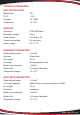
TECHNICAL PARAMETERS UNIT SPECIFICATION Modulation T.H.D Distance Temperture FM -0.8% 50-100M 14-131°F RECEIVER Sensitivity Removing weight Audio output Output connection Power supply 10UV/40DB emf 50ms 0-0.35Vp-p 5k 6.
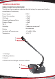
TECHNICAL PARAMETERS WIRELESS MEETING MICROPHONE The light on the microphone indicates that the battery has power and that the microphone is functioning. DC9V <35mA >90dB >80dB >80dB <3% Condenser noise proof Uni-direction -47 ±3dB @1KHz 14-131°F Power Supply Power Consumption S/N Ratio Channel Interference Ratio Dynamic Range T.H.D Cartridge Polarity Sensitivity of Transmission Temperture 1 2 1. Cartridge 2. Working indicator 3. Switch 4. Power and Low Voltage two color indicator 3 4 4 www.PyleUSA.
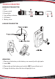
TECHNICAL PARAMETERS HANDHELD TRANSMITTER 1. Grill 2. Power switch 3. Power light 4. Low voltage indicator 5. 9V Battery 6. Battery cover LAVALIER TRANSMITTER OPERATION 1. Please put the battery in the battery case correctly with right poles 2. Switch ON 3. Please take out the battery and switch it OFF if you will not use it. 4. Change the battery when the low voltage light is on. 5 www.PyleUSA.
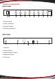
TECHNICAL PARAMETERS FRONT PANEL 1. Power Switch 2. Power Indicator 3. Volume Control 4. Receiving Indicator BACK PANEL 1. Antenna 2. Audio Output 3. Mixed-Balance Output 4. Balanced Output 5. DC Power 6 www.PyleUSA.
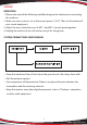
SYSTEM OPERATION 1. Please take note of the following workflow diagram for reference on connecting this machine. 2. Make sure your system is set to the correct power (110 V). Then set the volume of your sound equipment. 3. Adjust the mix so that the users of MIC 1 and MIC 2 sounds good together. 4. Unplug the machine if you will not be using it for a long time. SYSTEM CONNECTION FLOW DIAGRAM • Keep the machine at least 3 feet above the ground and 3 feet away from walls. • Pull the antenna upright.
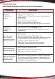
TROUBLESHOOTING Some common problems and their solutions are printed below. PROBLEM No sound; RF light(s) not glowing No sound; RF light(s) not glowing Received signal is noisy; contains extraneous sounds with transmitter on. SOLUTION • Make sure the transmitter • POWER switch is ON and the receiver is plugged into a power source • Check battery. • Check receiver squelch setting. • Check receiver antenna connection(s). • Make sure antennas are in line of sight of transmitter.