
User's Manual


Page 7
SVR-200 Service Manual
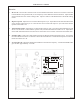
Pin 3: Remote enable/disable. Connect to the radio's auxiliary output or a separate switch to remotely enable
or disable the repeater. If this line goes high to activate the repeater, ensure that JP1 is set to the “+”
position. If this line goes to ground, set JP1 to the “-” position. J8 has two positions to add a pull up
(+) or pull down (-) resistor to this line if used with an open collector or dry contact output.
Pin 4: Mobile PTT output. Connect to mic PTT on the mobile radio, or a line that goes active low to transmit.
Pin 4 is an open collector output rated at 100mA at 50VDC.
Pin 5: 12 VDC input. Connect to the radios 12V switched supply or a point capable of supplying at least 1.5A
of current.
Pin 6: Mobile receive audio. Connect this line to the mobile receive audio path before the volume control.
If pin 6 is connected before de-emphasis, ensure that the SVR-200 receive path is programmed as flat
(common data). If connected after de-emphasis, program the receive path for pre-emphasis. Pin 6
is AC coupled and high impedance (>15K ohm). RV5 sets the receive audio level sensitivity; this input
should be between 30mVPP and 5VPP. J7 sets the gain of the receive input amp. If open, the input
has a maximum gain of one; if installed, the input has a maximum gain of 7.
Pin 7: Mobile COR detect. This line is used to indicate when the SVR-200 should repeat the transmission
to the handheld. Connect to a logic point in the radio that indicates proper tone and carrier have been
detected or the audio unmute line. If this line goes more positive during an unmute condition, program
the mobile COR line as active high (common data). If the line goes more negative during an unmute
condition, program the mobile COR line as active low. The input from pin 7 is high impedance and does
not have to go rail to rail. The SVR-200 uses a voltage comparator as a COR threshold detector. RV1
sets the mobile COR threshold level and should be set for half way between the mute and unmute levels
at pin 7. Example: If Pin 7 is connected to a point that goes from 0VDC (mute) to 5VDC (unmute),
set RV1 for 2.5VDC and program the mobile COR line as active high. If Pin 7 goes between 7.2VDC
(mute) and 5.8VDC (unmute), set RV1 for 6.5VDC and program the mobile COR line as active low.
Pin 8: Local mic audio. If programmed for local mic repeat, the SVR-200 will go into transmit mode and
repeat the audio from this line whenever the mobile radio is keyed by the local mic. Connect this line
to the mobile transmitter audio path before limiting or filtering. This input is AC coupled and high
impedance (>5.6Kohms). The input level at this pin should be 300mV to 5VPP. RV2 sets the local
mic sensitivity. If the mic high line has sufficient drive for this input, install J4 and leave pin 8
unconnected. J6 sets the gain of the local mic input amp. If open, the maximum gain is one; if installed,
the maximum gain is 10.
Pin 9: On-Air detect.
Trunking: Connect to a point in the radio that indicates the mobile transmitter is actually on the air.
This is not the same as mic PTT. If pin 9 goes positive during transmit, program the on-air detect line
for active high (common data). If pin 9 goes to ground during transmit, program the on air detect line
for active low.
Conventional: Used for local mic repeat indication from the mobile. Connect pin 9 to pin 4 of the
SVR-200 and program the on-air detect line for active low. Solder jumper J5 will connect pin 9 to pin
4 (PTT output) and can be used on conventional systems only. Do not install J5 for trunking
operation.
Install the SVR-200 in the vehicle using the supplied mounting bracket and hardware. Install the unit where
it will be easily visible by the driver and will not interfere with the drivers vision or constitute a hazard during a vehicle
collision. The SVR-200 mounts in the bracket using the four 8-32 x ¼" machine screws. Do not use longer screws
to mount the SVR-200 to the bracket or circuit damage may result.
Blue
Green
Red
Yellow
Violet
Brown
Gray