BridgeWay Ethernet to DeviceNet Gateway User Manual Part No. AB7603 Pyramid Solutions 1850 Research Drive, Suite 300 Troy, Michigan 48083 Phone 248-524-3890 Web www.pyramid-solutions.
Table of Contents i Table of Contents Preface......................................................................... iv How to Use This Manual ....................................... iv Important User Information ................................... iv Related Documentation........................................... v BridgeWay Module Description ............................. 1-1 Overview..................................................................... 1-1 Theory of Operation..........................
Table of Contents ii Slave Device Communication..................................... 5-2 Scan Cycles................................................................ 5-2 I/O Message Types .................................................... 5-3 I/O Mapping ................................................................ 5-3 Proxy for Group 2 Only Devices ................................. 5-3 Run/Idle Mode ............................................................ 5-4 Automatic Device Recovery (ADR) .......
Table of Contents iii The FTP Server .......................................................... 9-2 The Telnet Server....................................................... 9-2 HTTP Server............................................................... 9-8 SSI Functionality......................................................... 9-9 Email Client .............................................................. 9-23 Displaying I/O Data on a Web Page......................... 9-24 Status and Diagnostics.........
Preface iv Preface How to Use This Manual This manual provides an overview of the BridgeWay Ethernet to DeviceNet Gateway. It describes how to configure and operate it. Important User Information The data and illustrations found in this document are not binding. We reserve the right to modify our products in line with our policy of product development. The information in this document is subject to change and should not be considered as a commitment by Pyramid Solutions.
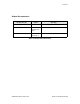
Preface v Related Documentation Document Name Author Web Page DeviceNet Specification ODVA www.odva.org EtherNet/IP Specification ControlNet International LTD. www.odva.org Modbus/TCP Schneider Automation www.modicon.com/openbus/index.html Table 2-1 Related Documentation © 2004 Pyramid Solutions Inc.
Chapter 1 Module Description 1-1 BridgeWay Module Description Overview The BridgeWay Ethernet to DeviceNet Gateway allows you to seamlessly connect your Information or Control level networks with your Device level network. The Ethernet to DeviceNet Gateway provides full DeviceNet Master functionality allowing connectivity to 63 DeviceNet slaves devices along with an Ethernet TCP/IP interface that supports IT protocols such as SMTP, FTP, HTTP and control protocols such as EtherNet/IP and Modbus/TCP.
Module Description 1-2 Theory of Operation The BridgeWay provides centralized data storage, the “PassageWayTM”, for data that is shared between the DeviceNet and Ethernet networks. Data is placed into the PassageWay by one network interface, allowing the data to be read through the other network interface.
Module Description 1-3 DeviceNet Features • DeviceNet Master scanner functionality supporting up to 63 DeviceNet slave devices • Explicit Messaging and Bit Strobe, Poll, and Change of State (COS) I/O connections. • Baud rates of 125, 250, and 500 Kbps. • Automatic baud rate detection option may be enabled or disabled. • Automatic Address Recovery can be configured to replace a faulted slave device with a replacement device at the same MAC ID.
Module Description 1-4 IT-Features • The BridgeWay features a flexible file system with two security levels. The size available for user files is approximately 1.4 Mbyte. • An FTP server provides easy file management using standard FTP clients. • A Telnet server featuring a command line interface similar to the MSDOS™ environment. • A a flexible HTTP server (Web server) with Server Side Includes (SSI) functionality. These are commands to the web server embedded in the HTML code.
Module Description 1-5 Optional Hardware • A PC with a serial RS232 COM port to be used by the BridgeWay Configuration Tool Software for downloading firmware updates. • RS232 null-modem cable (pins 2 and 3 swapped) from the PC to the BridgeWay module. • DIN rail to mount the BridgeWay. Required Software • DeviceNet configuration software such as RSNetWorx for DeviceNet to configure DeviceNet devices and BridgeWay’s DeviceNet operation. RSLinx version 2.31 or later is required.
Module Description 1-6 Hardware Description All connections, whether power or fieldbus, to the BridgeWay are made on one end of the module. Phoenix connectors are provided for power and DeviceNet connections. A RJ-style connector is provided for Ethernet connection. There is a 9-pin D-Subminiature connector for the auxiliary RS-232 port that is used for field firmware upgrades. See “Installation” on page 2-1 for more details on the connectors.
Chapter 2 Installation 2-1 Installation Installation and Operation Requirements •Power, input and output (I/O) wiring must be in accordance with Class 1, Division 2 wiring methods - article 501-4(b) of the National Electric Code, NFPA 70 and in accordance with local codes. •Warning - Explosion Hazard - Substitution of components may impair suitability for Class 1, Division 2. •Warning - Explosion Hazard - When in hazardous locations turn off power before replacing or wiring modules.
Installation 2-2 Power and Network Connections The power and network connections to the BridgeWay are made on the end of the module. Figure 2-1 indicates the location of each connector. DeviceNet Ethernet IP Address Power Aux RS-232 Ethernet Figure 2-1 BridgeWay Power and Network Connections © 2004 Pyramid Solutions Inc.
Installation 2-3 Connecting Power The power connection is a 2-pin terminal block located on the end of the module. The female terminal block connector is provided with the BridgeWay. Connections to be made are illustrated in Figure 2-2. 24VDC Common 24 VDC + Figure 2-2 Power Connection The BridgeWay requires 24 volts DC power. The module will start immediately when power is applied (There is no On/Off switch on the module). © 2004 Pyramid Solutions Inc.
Installation 2-4 Connecting DeviceNet The DeviceNet network connection is a 5-pin terminal block located next to the power connection on the end of the module. The female terminal block connector is provided with the BridgeWay. Connections to be made are illustrated in Figure 2-3. (Red) Net Power 24VDC + (White) CAN High CAN Shield (Blue) CAN Low (Black) Net Power 24VDC Common Figure 2-3 DeviceNet Connection A 120 ohm termination resistor (not provided) may be required for proper network termination.
Chapter 3 Configuration 3-1 Configuration This chapter describes how the BridgeWay Ethernet to DeviceNet Gateway is configured. The next chapter walks the reader through the configuration of the BridgeWay using the commonly available configuration tools. Ethernet Network Configuration Several methods may be used to set the IP Address. These methods include; IP Address Configuration Switch, DHCP/Bootp protocol, web browser, and the ARP protocol.
Configuration 3-2 DIP Switch Example Figure 3-1 IP Configuration DIP Switch The switches are set to 00010100 (20 decimal) (The switch position is shown in White in the diagram.) The IP address of the module will be set to 192.168.1.20. Note: The numbers on the switches on the IP configuration DIP switch do NOT correspond to bit locations in the address value. In fact, they are reversed. i.e. bit 0 is set by switch 8.
Configuration 3-3 Setting the IP Address Using Address Resolution Protocol (ARP) The module’s IP address can be changed using the ARP command from a PC. The new IP address will be stored in non-volatile memory. ARP requires the module’s Ethernet MAC Address that is printed on a label on the back of the module. Note: ARP cannot be used to change the subnet mask and gateway address of the BridgeWay. These can be configured using the BridgeWay’s Settings web page.
Configuration 3-4 Arp/Ping Example: The following commands will set the IP address of a BridgeWay with MAC address 00-30-11-02-00-5E to 65.106.34.252. arp -s 65.106.34.252 00-30-11-02-00-5e ping 65.106.34.252 arp -d 65.106.34.252 © 2004 Pyramid Solutions Inc.
Configuration 3-5 Setting the IP Address Using the Web Page The ethernet addresses can also be configured using the Status and Settings web page resident on the BridgeWay. The Status and Settings web page appears as shown below. Figure 3-2 Status and Settings Web Page © 2004 Pyramid Solutions Inc.
Configuration 3-6 The IP address, subnet mask, and default gateway address are displayed in the edit boxes on the web page. Changing any values and clicking the Submit Values button will set the addresses in the BridgeWay. Note that a power cycle or module reset is required for the changes to take effect. The Reset Module button can be used to reset the BridgeWay from the web browser. The Scanner Mode will display “RESETTING...” while the module resets and comes back online.
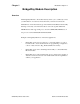
Configuration 3-7 IP Address Initialization The following flowchart describes how the IP configuration is determined when the BridgeWay is powered up. Start Valid Configuration File? No Yes Request config from DHCP/ BOOTP Server. Timeout 30 secs Use received configuration Yes Yes DHCP Config Received? DHCP Enabled? DIP Switch = 0 No DIP Switch = 0xFF Yes Yes No Enable ARP/Ping Address Option IP = 192.168.1.n Sub = 255.255.255.0 No Gateway IP = 192.168.1.255 Sub = 255.255.255.
Configuration 3-8 DeviceNet Network Configuration DeviceNet MAC ID The DeviceNet MAC ID is software configurable; there are no switches used to set it. When first powered, the factory default configuration sets the MAC ID to 63. The allowable range for MAC ID is 0 - 63. A DeviceNet node commissioning tool (e.g. RSNetWorx or NetTool-DN) is used to set the MAC ID to the desired value for the application. The value is stored in non-volatile memory and used on subsequent power ups.
Configuration 3-9 EDS File Each device on a DeviceNet network has an associated EDS file containing all necessary information about the device. This file is used by the network configuration tools, such as RSNetWorx or NetTool-DN, during configuration of the network. The laster version of the EDS file for the BridgeWay can be downloaded from Pyramid Solution’s web site, or received by contacting Pyramid Solutions. © 2004 Pyramid Solutions Inc.
Configuration 3-10 DeviceNet I/O Configuration I/O Mapping The DeviceNet I/O configuration defines the format of the Input and Output tables in the PassageWay, or the mapping of DeviceNet slaves’ I/O data to the I/O tables. See “Theory of Operation” on page 1-2 for a discussion on the PassageWay and the use of I/O tables in the BridgeWay. As slaves are added to the BridgeWay’s DeviceNet scanner configuration, the location in the I/O tables of each part of the slave’s I/O data is determined and stored.
Chapter 4 Quick Start 4-1 Quick Start This chapter provides a step by step explanation of configuration of the BridgeWay Ethernet to DeviceNet Gateway. It is intended to be used as a beginner’s guide to configuring and using the BridgeWay using RSNetWorx for DeviceNet or NetTool-DN. It also demonstrates how easy it is to create your own webpage and upload it to the module. Requirements: An Ethernet network and a PC connected to that network, running Windows™ 98/ME/2000/XP, Microsoft Internet Explorer 5.
Quick Start 4-2 Step 2: Locate the module is on the network. • RSNetWorx allows browsing on the network to identify devices. • Select the Network menu option and pull down menu. • Select the Single Pass Browse option and wait for browsing to complete. If this is the first time RSNetWorx has been used with a BridgeWay, the BridgeWay’s icon should indicate “Unrecognizable Device”. Step 3: Register the BridgeWay EDS file in RSNetWorx.
Quick Start 4-3 Step 5: Set the DeviceNet MAC ID and Baud Rate • Select the Tools menu option and pull down menu. • Select the Node Commissioning option. Another screen appears. • Click on Browse and choose the DeviceNet network. • When the browse is completed, double click on the BridgeWay icon. • Enter the desired MAC address and/or baud rate, then click the Apply button. Note: The BridgeWay will automatically reset if a new MAC ID is entered.
Quick Start 4-4 Step 6: Enabling the Autobaud Option If it is desirable to have the BridgeWay automatically determine the network baud rate, the Autobaud option must be enabled. • Highlight the BridgeWay module by left clicking on its icon. • Select the Device menu option and pull down menu. • Select the Class Instance Editor option. A pop up Message box appears. Click on Yes. Another screen appears. • There are several parts to this screen.
Quick Start 4-5 Node Commissioning with NetTool-DN Step 1: Connect the module to your network • Make sure a PC running NetTool-DN (version 1.0.0.1 or later) is connected to the DeviceNet network via the NetTool-DN RS-232 interface adapter. • With the BridgeWay un-powered, connect the DeviceNet network cable to the DeviceNet connector of the module. (See “Connecting DeviceNet” on page 2-4) • Power up the BridgeWay. Step 2: Locate the module is on the network. • Start NetTool-DN on the PC.
Quick Start 4-6 Step 3: Register the BridgeWay EDS file with NetTool-DN NetTool-DN requires an electronic data sheet (EDS) to recognize a device and its capabilities. An EDS file is available on the Pyramid Solutions web site. The EDS file must be registered with NetTool-DN before configuration can continue. • From the Tools menu, select Install EDS Files. • Enter the path, or browse to the location of the EDS file for the BridgeWay. • Click Open.
Quick Start 4-7 Step 6: Enabling the Autobaud Option If it is desirable to have the BridgeWay automatically determine the network baud rate, the Autobaud option must be enabled. • Highlight the BridgeWay module by right clicking with the cursor on its icon. • Select the Device menu option and pull down menu, then select Properties. A parameter screen is displayed. • Click on Upload. The parameter values will be read from the device. • Put the cursor “Autobaud” parameter value.
Quick Start 4-8 DeviceNet I/O Configuration DeviceNet I/O configuration involves using a DeviceNet configuration tool to set the BridgeWay’s scan list and I/O table mapping. The following sections explain how this is done using either Rockwell Software’s RSNetWorx for DeviceNet or HMS’ NetTool-DN.
Quick Start 4-9 • Select the Output tab. The Output mapping screen is displayed. The top portion gives a list of the devices in the scan list that the BridgeWay will send output data to. The bottom shows the location in the Output table where the data will be placed for each device. This shows the format of the Output table of the BridgeWay. This is the format of the output data that will be sent to the BridgeWay from the EtherNet/IP scanner.
Quick Start 4-10 I/O Configuration Using NetTool-DN Step 1: Set up BridgeWay module’s DeviceNet Scanlist In most cases it will be necessary to return the BridgeWay to Idle mode as described in “Step 4: Put the BridgeWay in Idle Mode” on page 4-6. Once in Idle mode the following steps should be taken to configure the scan list. • From the network display screen right click on the BridgeWay icon and select Device. Pull down its associated menu and select Properties. This displays the Parameters screen.
Quick Start 4-11 Ethernet Network Configuration Step 1: Connect the BridgeWay Module to Your Network • Connect the Ethernet network cable to the RJ-45 fieldbus connector on the end of the BridgeWay. Step 2: Configure the BridgeWay IP Address Using Arp/Ping • Set all 8 switches on the IP Address Configuration DIP switch to the ON position. • Turn the power ON. • Open an MS-DOS™ window on the PC.
Quick Start 4-12 • You should see a message similar to below indicating a connection. Example: Reply from 65.106.34.252 Bytes=32 Time=271ms TTL=30 • Type ‘arp -d ’ Example: arp -d 65.106.34.252 The BridgeWay module will now adopt the IP address that was specified in the ‘arp -s’ command. • Set all 8 switches on the IP Address Configuration DIP switch to the OFF position. © 2004 Pyramid Solutions Inc.
Quick Start 4-13 Using the Ethernet File System Step 1: Browse the file system • Open a web browser window on the PC. • Type ‘FTP://’ in the address field. (Substitute with the IP address you are using for the module). (Don’t include the “<“or “>” characters.) • When prompted for a username enter “admin”. • When prompted for a password enter “admin”. You can now browse the file system. You should see subdirectories “/web”, “/ pswd” and “/user” and three files “/index.
Quick Start 4-14 • Exit the telnet program. • Open a web browser window on the PC. • Type ‘FTP://’ in the address field. Substitute with the IP address you are using for the module. Don’t include the “<“or “>” characters • The directory and file that you created earlier using the Telnet application should appear. (If your files are not present, press ‘F5’ to update the window content) • Don’t close this window yet. If you are not in the root directory, make sure you are.
Quick Start 4-15 Step 4: View a Web Page • Open a web browser window on the PC. • Type ‘HTTP:///hello.htm’ in the URL field. (Substitute with the IP address you are using for the module). Don’t include the “<“or “>” characters. • The web page that you downloaded in the previous step should be displayed in the browser. © 2004 Pyramid Solutions Inc.
Chapter 5 DeviceNet 5-1 DeviceNet Interface Network Communications The BridgeWay Ethernet to DeviceNet Gateway acts as a DeviceNet Master or a slave. The BridgeWay, as a master, can exchange I/O data with up to 63 nodes. The module can also act as a slave to another DeviceNet Master, exchanging the contents of its I/O tables with the master. Configuration The BridgeWay is configured using a DeviceNet configuration tool such as RSNetWorx for DeviceNet or NetTool-DN.
DeviceNet 5-2 Slave Device Communication The BridgeWay continuously attempts to establish connections with devices configured in the scan list (list of configured slaves). Once connections are established, the module performs all necessary steps to configure the required I/O messaging. The BridgeWay provides explicit message proxy services for all group 2 only slaves. Once any Group 2 only devices are configured, the BridgeWay sends “keep alive” messages to the devices in addition to the I/O messages.
DeviceNet 5-3 I/O Message Types The BridgeWay supports all I/O messaging types specified by the DeviceNet protocol. These include strobe, poll, COS, COS Unacknowledged, Cyclic, and Cyclic Unacknowledged I/O messages. I/O messaging and I/O parameters are configured using the DeviceNet configuration tool. I/O Mapping The contents and layout of the data in the I/O tables is defined during configuration of the scan list.
DeviceNet 5-4 Run/Idle Mode The BridgeWay has two modes of operation, Run and Idle. In both modes the BridgeWay’s DeviceNet master maintains communication with slave devices in its scan list. In Run mode the BridgeWay sends output data to the slaves and receives input data. Since it is actively sending output data affecting slave device operation, the BridgeWay rejects attempts to alter its configuration and disrupt communications; it must first be put in Idle mode.
DeviceNet 5-5 Automatic Device Recovery (ADR) This is a feature of the DeviceNet master which allows a slave node that has dropped off the network (Fault, power loss, etc.) to be replaced with another device of the same type. There are 2 parts to ADR, Address Recovery, and Configuration Recovery. Note: ADR is only available when using Rockwell Software’s RSNetWorx for DeviceNet as the configuration tool.
DeviceNet 5-6 Interaction with I/O Tables The DeviceNet interface in the BridgeWay accesses the I/O tables as slave I/O connections are processed by the DeviceNet master; there is no buffering or timed updates of the I/O within the module. Safeguards are in place to ensure data integrity by prohibiting simultaneous access by the Ethernet and DeviceNet interfaces. There is no synchronization between the 2 network interfaces.
Chapter 6 EtherNet/IP 6-1 EtherNet/IP Interface EtherNet/IP is based on the Control and Information protocol (CIP) which is also the application layer for DeviceNet to exchange data between nodes. Product Features The BridgeWay contains EtherNet/IP Adapter Class functionality. Being an I/O Server it can respond to requests for I/O messages but it does not generate such requests. A Scanner device would generate these requests. The BridgeWay supports Message Server and Message Client, functionality.
EtherNet/IP 6-2 CIP Messaging Two types of messaging are used. The regular or repeated transport of a specific set of data items is known as Implicit Messaging. Both parties agree in advance and allocate resources for the data being transported. The connection ID within the Implicit message defines the meaning of the data and establishes the transport rate and transport class. The term Implicit Messaging can be interchangeable with the term I/O Messaging.
EtherNet/IP 6-3 I/O Messaging The BridgeWay allows an EtherNet/IP scanner access to the I/O data of DeviceNet slaves. The data produced by the DeviceNet slaves is collected in the Input Table (IN) of the BridgeWay and becomes the EtherNet/IP Input I/O to the EtherNet/IP scanner. EtherNet/IP Output data from the scanner is stored in the BridgeWay’s Output Table (OUT) and sent to the DeviceNet slaves which consumes it.
EtherNet/IP 6-4 Assembly Objects and Connections There are 3 Assembly Object instances accessible from EtherNet/IP: input, output and status. The input and output assemblies are linked to the input and output data tables. The status assembly provides current status information about the BridgeWay. The assembly instances associated with these 3 assemblies are listed below.
EtherNet/IP 6-5 Input Assembly The input assembly contains a 32-bit status register followed by the data in the BridgeWay’s input data table. Byte Offset Size in Bytes Description 0 4 Status register. 4 Up to 504 Input data. Table 6-3 Input Assembly Format The input data format and content is determined by the DeviceNet scanner configuration. The data appears in the table as it is mapped from the DeviceNet input connections.
EtherNet/IP 6-6 Output Assembly The output assembly contains a 32-bit run/idle register and a 32-bit command register followed by the data in the BridgeWay’s output data table. Byte Offset Size in Bytes Description 0 4 Run/Idle register. 4 4 Command register. 8 Up to 500 Output data. Table 6-5 Output Assembly Format The output data format and content is determined by the DeviceNet scanner configuration. The data appears in the table as it is mapped to the DeviceNet output connections.
EtherNet/IP 6-7 The Command register is a bit string with the following bit definitions. Bit Description 0 Local Run Mode. Used in conjunction with the System Run Mode bit in the Command register to determine the run mode of the BridgeWay. Both bits must be set for the BridgeWay to be in Run mode; otherwise the module will be in Idle mode. 1 Fault. Sets a fault condition in the BridgeWay. 2 Disable DeviceNet network. 3 Not used. 4 Reset the BridgeWay module. 5-31 Not used.
EtherNet/IP 6-8 Status Assembly The status assembly is a collection of status and diagnostic information for the BridgeWay DeviceNet interface. The information in the assembly is updated once a second. Note: All information in the status assembly is stored in little endian format. The least significant byte of multi-byte values is stored first.
EtherNet/IP 6-9 Byte Offset Size in Bytes Data Type Name Description 36 4 ASCII[4] Status Display Mimics a 4-character alpha-numeric display. If there are no faults, the display indicates the BridgeWay MAC ID and its Run/Idle status. If there are faults, the display will scroll through the MAC IDs of the faulted nodes and display the error code associated with each. See Table 10-6, “Node Status Codes,” on page 10-5 for a list of error codes.
EtherNet/IP 6-10 Notes About Using ControlLogix I/O Connections When configuring I/O connections between a Rockwell Automation ControlLogix EtherNet/IP scanner and the BridgeWay, the Generic EtherNet/IP device type should be used. The Run/Idle register is automatically inserted at the front of the output data and the application has no control over its use. The System Run Mode bit is set according to the Run/Program mode of the controller.
EtherNet/IP 6-11 CIP Bridging The EtherNet/IP protocol provides bridging capabilities to allow a device on the EtherNet/IP network to access a device on the DeviceNet network through Explicit Messaging. The BridgeWay Ethernet to DeviceNet Gateway allows a device on EtherNet/IP to send an Explicit Message to a device on DeviceNet and receive its response. In this way the device on EtherNet/IP can directly access the objects of any DeviceNet device to configure or access data.
Chapter 7 Modbus/TCP 7-1 Modbus/TCP Interface The BridgeWay supports Modbus/TCP commands. The implementation of the Modbus/TCP server is done according to the Modbus/TCP specification 1.0. All commands according to class 0 and class 1 are implemented and a subset of the class 2 commands. The module can handle 8 simultaneous connections. Supported Commands The following Modbus/TCP commands are supported by the BridgeWay.
Modbus/TCP 7-2 Supported Exception Codes An exception code is returned in the response when the BridgeWay is unable to service the Modbus request that was received. The following exception codes will be used by the BridgeWay.
Modbus/TCP 7-3 Modbus/TCP Addressing The BridgeWay’s Input (IN) and Output (OUT) areas are set to a maximum size of 508 bytes each. The Status assembly area is 128 bytes. When accessing these areas, with Modbus commands, the addressing is done according to the following tables. Word Bit Address 000h 0000h 0001h 0002h 0003h 0004h 0005h 0006h ... 000Eh 000Fh 001h 0010h 0011h 0012h 0013h 0014h 0015h 0016h ... 001Eh 001Fh 0FD0h 0FD1h 0FD2h 0FD3h 0FD4h 0FD5h 0FD6h ...
Modbus/TCP 7-4 Bit Addressing Examples • To reference the first bit of the Input Table use address 0000h. • To reference the 15th bit of the Input Table use address 000Eh (14 decimal). • To reference the first bit of the Output Table use address 4000h (16384 decimal). • To reference the 100th bit of the Output Table use address 4063h (16483 decimal). Word Addressing Examples • To reference the first word of the Input Table use address 000h.
Modbus/TCP 7-5 I/O Data Format The BridgeWay transfers I/O data between Modbus/TCP and DeviceNet without regard to data content or format. Due to this, the user is responsible for making sure that the devices on either network understand the format of the data. DeviceNet is a little endian protocol; values are transmitted least significant byte first. Hence, all data in the I/O tables is assumed, by the DeviceNet nodes, to be stored as little endian.
Chapter 8 File System 8-1 File System The files system is a fixed-size storage area with a hierarchical directory structure. Any data, user or application can be stored in files within the file system. Files can be grouped in directories for readability. The file system features two security levels. Depending on security level, different users can have access to different files and directories. The file system is accessible via FTP, Telnet, and HTTP.
File System 8-2 Security The file system features two security levels: Administration and Normal. In Administration mode, the user has full access to the file system through FTP and Telnet. This enables the user to access areas of the file system that are restricted or inaccessible in Normal mode. Normal mode is recommended for normal operation, so that web pages and other settings are protected. Administration mode is intended for product development.
File System 8-3 To prevent unauthorized access this should be changed as soon as possible. This can be done by changing the username or password. The Administrator can access this file to add or remove users or change passwords. If a user logs into Telnet or FTP using a username/password combination found in the admin password file (see “Password Files” on page 8-11) he will gain access to the entire system.
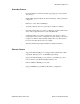
File System 8-4 Structure The figure below illustrates the structure of the file system, where the system files are located, and which areas that can be accessed by normal/admin users. Root directory in admin mode Root directory for normal users user index.htm (default web page) User1 ethcfg.cfg (Ethernet settings, IP etc) User2 ip_access.cfg (IP Addresses of allowed clients) telwel.cfg (Telnet welcome message) pswd onoffln.cfg (ON/OFF-line configuration web sys_pswd.
File System 8-5 Default Files The following directories are already created on the BridgeWay when first powered; \pswd, \user, \web, \web\styles, \user\pswd. The following files are also on the BridgeWay; \pswd\ad_pswd.cfg, \telwel.cfg, \ethcfg.cfg, \index.htm \user\pswd\sys_pswd.cfg. These files can be edited as needed. Each file is discussed below. The BridgeWay power must be recycled for any changes to take effect. © 2004 Pyramid Solutions Inc.
File System 8-6 Virtual File System The module contains a virtual file system, a set of files used to build the default configuration web page. These are hidden files. The files can be replaced or disabled, but not erased. A file with the same name in the file system replaces the file in the virtual file system until it is removed. The virtual file system contains the following files: index.htm config.htm configform.htm store.htm logo.gif configuration.gif boarder.bg.gif boarder_m_bg.
File System 8-7 Configuration Files ‘ethcfg.cfg’ This file contains the network configuration and is read by the module at start up. The settings in this file are affected by SSI commands. The components and format of the file is shown below: [IP address] IP address 10.10.12.212 [Subnet mask] Subnet mask 255.255.255.0 [Gateway address] Gateway address 0.0.0.0 [SMTP address] SMTP address – This must be configured in 0.0.0.
File System 8-8 The contents of this file can be redirected by placing the line ‘[File path]’ on the first row, and a file path on the second. Example: [File path] \user\eth_settings.cfg In this example, the settings described above will be loaded from the file ‘user\eth_settings.cfg’. This permits normal users to access the network configuration settings. Note: The module needs to be restarted for changes in this file to have affect. ‘ip_accs.
File System 8-9 Example: [Web] 10.10.12.* 10.10.13.* [FTP] 10.10.12.* [Telnet] 10.10.12.* [All] *.*.*.* The above example will allow all IP addresses beginning with 10.10.12 to access all protocols in the module. IP numbers beginning with 10.10.13 will not be able to access the FTP and Telnet servers. The Modbus/TCP and EtherNet/IP servers will accept connections from any IP address.
File System 8-10 ‘onoffin.cfg’ The ON/OFF line functionality is by default configured to be triggered by the Link Status. It can however be configured to be triggered by for example a Modbus command. This is done by creating the file ‘\onoffln.cfg’. The components and format of the file is shown below: [ON/OFF-line trigger] ON/OFF-line trigger [‘Link’|’Modbus’] Modbus Values “Link” and “Modbus” [Timeout] Timeout value.
File System 8-11 Password Files ‘sys_pswd.cfg & ad_pswd.cfg’ These files contain user / password information for users in normal mode (‘sys_pswd.cfg’) and administration mode (‘ad_pswd.cfg’). The files shall be located in ‘\user\pswd’ and ‘\pswd’ respectively. These directories are protected from web browser access. The file format is the following: User1:password1 User2:password2 ... UserN:passwordN Example: JohnQ:Password In this example, the username is ‘JohnQ’, and the password is ‘Password’.
File System 8-12 ‘web_accs.cfg’ Files within the file system can be protected from web access through username/ password protection. To put username/password protection to files, a file called ‘web_accs.cfg’ must be located in the same directory as the files to protect. If this file is available, all files within that directory and its subdirectories will be protected. Multiples of these password files may be present in the system, giving different users access to different files and directories.
File System 8-13 Other Files ‘telwel.cfg’ The default Telnet welcome message can be changed by creating this file. It shall contain the new welcome message in ASCII form. The contents of this file can be redirected by placing the line ‘[File path]’ on the first row, and a file path on the second. Example: [File path] \my_settings\telnet_welcome_message.txt In this example, the welcome message will be loaded from the file ‘\my_settings\telnet_welcome_message.txt’. © 2004 Pyramid Solutions Inc.
File System 8-14 Email files (email_1.cfg,email_2.cfg to email_10.cfg) These files contain predefined email messages and information on how and when to send them. It is possible to have a maximum of 10 admin defined email files and 10 user defined email files. The files must be named ‘email_1.cfg’... ‘email_10.cfg’, and placed in the folders ‘\email’ and ‘\user\email’ respectively. If the SMTP server is not configured the email will not be sent (See “‘ethcfg.cfg’” on page 8-7).
File System 8-15 Parameter Values Description Area IN OUT Source area in Input/Output Offset a hexadecimal (0xN) or decimal value Source Offset in Input/Output Type byte word long Source data type Match Value a hexadecimal (0xN) or decimal value Value to compare with source value.
File System 8-16 Example [Register] IN, 0x0003, byte A byte is read from the Input area at location 3. [Register match] 0x20, 0x7F, > Mask Input byte with 0x7F, if result greater than 0x20 send email. [To] support@your_company.com [From] YourDevice@your_network.com [Subject] Status [Message] Data out of range © 2004 Pyramid Solutions Inc.
File System 8-17 BridgeWay Web Page Files The BridgeWay contains several web pages in HTML files to allow changing the default configuration settings and displaying DeviceNet status. Information displayed on these pages are updated every 2.5 seconds. NOTE: These web pages require that your browser support Java. Recent versions of Microsoft Internet Explorer do not support Java by default. The Microsoft Virtual Machine for Internet Explorer may be downloaded from Microsoft’s web site at http://v4.
File System 8-18 ‘\web\BW_NodeIdle.htm’ (Idle Nodes) Click on the “Idle Nodes” link to display a web page providing a status table of the possible 63 DeviceNet nodes with an indication of whether each node is idle or in a configuration state. This is valid for nodes configured in the BridgeWay’s scanlist. Each MAC ID will have the word “Idle” or a dash (-) next to it. ‘\web\BW_NodeFaulted.
Chapter 9 IT Functionality 9-1 IT Functionality The module features common IT functionality such as an HTTP server, FTP server, an Email client, and a Telnet server. This provides easy file management and the possibility to customize the module to provide user-friendly access to parameters. Also, the module can be configured to report selected information via Email using the Email client. Default User Accounts The BridgeWay contains two user accounts on initial power up.
IT Functionality 9-2 The FTP Server It is possible to upload/download files to/from the file system using a standard FTP client. Depending on security settings, different parts of the file system can be accessed by the user: Normal Mode / Normal User The user must login using a valid username/password combination. The root directory will be the ‘\user’ directory unless the user has admin permission, see below. Administration Mode / Admin User The admin user has unrestricted access to the file system.
IT Functionality 9-3 General Commands admin Usage: admin Provided that the user can supply a valid admin username/password combination, this command enables admin access in normal mode. This command has no affect in administration mode.
IT Functionality 9-4 Diagnostic Commands The following commands can be viewed by the command ‘help diagnostic’ arps Usage: arps Display ARP stats and table iface Usage: iface Display net interface stats sockets Usage: sockets Display socket list routes Usage: routes Display IP route table © 2004 Pyramid Solutions Inc.
IT Functionality 9-5 File System Operations For commands where filenames, directory names or paths shall be given as an argument the names can be written directly or within quotes. For names including spaces the filenames must be surrounded by quotes. It is also possible to use relative pathnames using ‘.’, ‘\’ and’.’. dir Usage: dir [path] Lists the contents of a directory. If no path is given, the content of the current directory is listed. md Usage: md [[path][directory name]] Creates a directory.
IT Functionality 9-6 format Usage: format Formats the file system. This is a privileged command and can only be called in administration mode. del Usage: del [[path][filename]] Deletes a file. ren Usage: ren [[path][old name]] [[path][new name]] Renames a file or directory. move Usage: move [[source path][source file]] [[destination path]] This command moves a file or directory from the source location to a specified destination.
IT Functionality 9-7 type Usage: type [[path][filename]] Types the contents of a file. mkfile Usage: mkfile [[path][filename]] Creates an empty file. append Usage: append [[path][filename]] [“The line to append”] Appends a line to a file. © 2004 Pyramid Solutions Inc.
IT Functionality 9-8 HTTP Server The module features a complete HTTP (web) server with Server Side Includes (SSI) functionality. Server Side Includes are commands to the web server embedded in the HTML code. When the web server encounters the commands the results of the command are inserted in the web page. SSI commands allow easy access to the IN and OUT areas of the BridgeWay module.
IT Functionality 9-9 Security All files except files in the directories “\user\pswd\”, “\pswd\” and files named ‘web_accs.cfg’ can be viewed by default. Other directories can be protected by placing a file called ‘web_accs.cfg’(see “Password Files” on page 8-11) in the directory to protect. The file contains a list of users that are allowed to browse that directory. Also, it is possible to configure which IP addresses are allowed to connect to the web sever, “‘ip_accs.cfg’” on page 8-8.
IT Functionality 9-10 DisplayGateway This function returns the currently used Gateway address. Syntax: DisplayDhcpState This function returns whether DHCP/BootP is enabled or disabled. Syntax: DisplayEmailServer This function returns the current SMTP server address. Syntax: © 2004 Pyramid Solutions Inc.
IT Functionality 9-11 Store Function StoreEtnConfig This SSI function stores a passed IP configuration to FLASH. Syntax: Include this line in a HTML page and pass a form with new IP settings to it.
IT Functionality 9-12 Formatted Display printf This SSI function includes a formatted string, which may contain data from the Input (IN) Output (OUT) area, on a web page. The formatting of the string is equal to the standard C function printf(). Syntax:
IT Functionality 9-13 Between the “%” and the conversion character there may be the following modifiers: Modifier Description - Specifies left adjustment of the converted argument in its field. + Specifies that the number will always be printed with a sign. space If the first character is not a sign, a space will be prefixed. 0 Specifies padding to the field with leading zeroes. # Specifies an alternate output form. For o, the first digit will be zero.
IT Functionality 9-14 The conversion characters and their meaning are shown below. If the character after the “%” is not conversion character, the behavior is undefined.
IT Functionality 9-15 The arguments that can be passed to the SSI function printf are: Argument Description InReadSByte(offset) Reads a signed byte from position offset in the Input (IN) area InReadUByte(offset) Reads a unsigned byte from position offset in the IN area InReadSWord(offset) Reads a signed word (short) from position offset in the IN area InReadUWord(offset) Reads a unsigned word (short) from position offset in the IN area InReadSLong(offset) Reads a signed longword (long) from posi
IT Functionality 9-16 Note: The I/O data is stored in the same format as it is received and sent on the DeviceNet network. DeviceNet is a little endian protocol; values are transmitted least significant byte first. Hence, all data in the I/O tables is assumed, by the DeviceNet nodes, to be stored as little endian. The web server operates in a big endian environment. Some data may have to be manipulated to account for byte ordering when displaying it on a web page. © 2004 Pyramid Solutions Inc.
IT Functionality 9-17 Formatted Input scanf This SSI function reads a string passed from an object in a HTML form, interprets the string according to the specification in format, and stores the result in the Output (OUT) area according to the passed arguments. The formatting of the string is equal to the standard C function call scanf(). Syntax:
IT Functionality 9-18 The conversion characters d, i, o, u and x may be preceded by the letter “l” to indicate that a pointer to ‘long’ appears in the argument list rather than a ‘byte’ or a ‘short’ The arguments that can be passed to the SSI function scanf are: Argument Description OutWriteByte(offset) Writes a byte to position offset in the OUT area OutWriteWord(offset) Writes a word (short) to position offset in the OUT area OutWriteLong(offset) Writes a long to position offset in the OUT area O
IT Functionality 9-19 Text Function GetText This SSI function gets the text from an object and stores it in the OUT area. Syntax: offset specifies the offset from the beginning of the OUT area. n (optional) specifies maximum number of characters to read Default output: Success - Write succeeded Failure - Write failed © 2004 Pyramid Solutions Inc.
IT Functionality 9-20 File Functions IncludeFile This SSI function includes the contents of a file on a web page. Syntax: Default output: Success - Failure - Failed to open SaveToFile This SSI function saves the contents of a passed form to a file. The passed name/ value pair will be written to the file “File name” separated by the “Separator” string.
IT Functionality 9-21 String Functions Changing SSI Output There are two methods of changing the output strings from SSI functions: • Changing SSI output defaults by creating a file called “\ssi_str.cfg” containing the output strings for all SSI functions in the system. • Temporary changing the SSI output by calling the SSI function “SsiOutput()”. SSI Output string file If the file “\ssi_str.
IT Functionality 9-22 [SaveToFile] Success: “String to use on success” Failure: “String to use on failure” To include filename “%s” can be included to the string once. [GetText] Success: “String to use on success” Failure: “String to use on failure” The contents of this file can be redirected by placing the line [File path] on the first row, and the actual file path on the second row.
IT Functionality 9-23 Email Client It is possible to send predefined email messages to predefined receivers triggered by an event in the IN/OUT area. This area is scanned every 5 seconds. The IP address to a SMTP (mail) server must be configured (See“‘ethcfg.cfg’” on page 87). The SMTP server must not require a username/password for access. It is possible to have 10 user defined, and 10 admin defined emails triggered on different events.
IT Functionality 9-24 Displaying I/O Data on a Web Page The following is an example of an HTML file that when uploaded to the module displays in hex the second byte of data from the IN able and the third byte of data of the OUT table using the SSI “printf” command.
Chapter 10 Status and Diagnostics 10-1 Status and Diagnostics BridgeWay LEDs There is a group of LED indicators on the front of the BridgeWay that is used to annunciate the current status of the module and the network interfaces. The layout of the LEDs is shown in Figure 10-1.
Status and Diagnostics 10-2 DeviceNet Network Status LED State Summary Description Solid Green Online and communicating The BridgeWay is on the DeviceNet network and communicating with at least 1 device. Flashing Green Online, no communication The BridgeWay is on the DeviceNet network and is not currently communicating with any devices. Solid Red DeviceNet interface fault A major fault in the DeviceNet interface has been detected. Possible causes include Bus-off or duplicate MAC ID.
Status and Diagnostics 10-3 Ethernet Activity LED The Ethernet Activity LED flashes green as Ethernet packets are received or transmitted. Ethernet Link LED The Ethernet Link LED indicates that the module is connected to an Ethernet network. The LED will display solid green if there is a valid physical link. Ethernet Module Status LED State Summary Description Off No Power Not powered Solid Green Normal The module is operating correctly.
Status and Diagnostics 10-4 Ethernet Network Status LED State Summary Description Off No Power The module has no power or no IP address assigned. Solid Green Network OK and communicating There is at least one EtherNet/IP connection. (Not affected by Modbus/TCP connections.) Flashing Green Network OK There are no active connections. (Not affected by Modbus/TCP connections.) Solid Red Address conflict The module’s IP address is already in use by another module.
Status and Diagnostics 10-5 Faulted Nodes Web Page The Faulted Nodes page indicates which DeviceNet nodes are currently in a faulted state. If a node is faulted, the page will display “Faulted” next to the node’s MAC ID. Note that only nodes which are configured as slaves to the BridgeWay and the BridgeWay itself are updated on this page. A node is considered faulted if the BridgeWay has lost communications or is unable to establish communications with the node.
Status and Diagnostics 10-6 Status Code Description 74 CAN receive overrun error. 75 CAN network failure. 76 Scanner is lonely; it is not receiving any network traffic. 77 Incorrect connection size. 78 No response from the device. 79 CAN transmit failure. 80 In Idle mode. 81 Faulted. 82 DeviceNet fragmentation error. 83 Error during slave connection initialization. 84 Slave connection initialization in progress. 85 Incorrect data size received on connection.
Status and Diagnostics 10-7 Status Assembly The status assembly is an assembly object instance that is accessible from EtherNet/IP both explicitly and using an I/O connection. The status assembly contains current status and diagnostic information pertaining to the BridgeWay’s DeviceNet interface. See “Status Assembly” on page 6-8 for complete details of the format and content of the assembly. © 2004 Pyramid Solutions Inc.
Chapter 11 Specifications 11-1 Specifications Environmental Specifications Temperature Operating: 0 to 70 degrees Celsius Non-Operating: -25 to 85 degrees Celsius EMC Directive Compliance This product is tested to meet the Council Directive 89/336/EC Electromagnetic Compatibility (EMC) by applying the following standards, in whole or in part, documented in a technical construction file: • EN50081-2-EMC Generic Emission Standard, Part 2 - Industrial Environment • EN50082-2-EMC Generic Immunity Standar
Specifications 11-2 Mechanical Specifications Mechanical Rating IP20/NEMA 1 Dimensions Figure 11-1 BridgeWay Mechanical Dimensions I/O Data Sizes Input Maximum 508 bytes Input Output Maximum 508 bytes Output Status 128 bytes of Status data © 2004 Pyramid Solutions Inc.
Chapter 12 Connectors 12-1 Connectors Power Figure 12-1 Power Connector Pin Connection 1 24 VDC + 2 24 VDC Common Table 12-1 Power Connector Pin Definitions Use Phoenix connector part number MSTB 2,5/2-ST-5,08 ABGY © 2004 Pyramid Solutions Inc.
Connectors 12-2 DeviceNet Pin Signal 1 V- 2 CAN_L 3 Shield 4 CAN_H 5 V+ Table 12-2 DeviceNet Pinout Use Phoenix connector part number MSTB 2,5/5-ST-5,08-ABGYAU © 2004 Pyramid Solutions Inc.
Connectors 12-3 Ethernet RJ45 Pin Signal 1 TD+ 2 TD- 3 RD+ 4 Termination 5 Termination 6 RD- 7 Termination 8 Termination Table 12-3 RJ45 Pinout © 2004 Pyramid Solutions Inc.
Connectors 12-4 Auxiliary RS-232 9 Pin D-Subminiature Pin Signal 1 NC 2 Receive 3 Transmit 4 NC 5 NC 6 NC 7 NC 8 NC 9 NC Table 12-4 RS232 9 Pin © 2004 Pyramid Solutions Inc.
Chapter 13 Warranty 13-1 Warranty Pyramid Solutions warrants all new products to be free of defects in material and workmanship when applied in the manner for which they were intended and according to Pyramid Solutions’ published information on proper installation. The Warranty period is one year from the date of shipment.
Chapter 14 Support 14-1 Support Technical Product Assistance If you need to contact Pyramid Solutions for technical assistance, ask for BridgeWay technical support at: 1-248-524-3890. You can obtain technical assistance by email at: ProductSupport@pyramid-solutions.com. You can also obtain technical assistance and download documentation and firmware updates online at: http:/www.pyramid-solutions.com/Expertise_DataCom_Support.htm. Contact Information Pyramid Solutions, Inc.