Operating and Installation Manual for PYRAMID DSP 120-160kVA Uninterruptible Power Systems USER MANUAL
CONTENTS SAFETY ...................................................................................................................................................1 I. GENERAL DESCRIPTION ..............................................................................................................2 1.1 Introduction ...............................................................................................................................2 1.2 Design Concept ..............................................
VI. MAINTENANCE ...............................................................................................................................29 6.1 Scheduled Maintenance ...........................................................................................................29 6.2 Daily checks..............................................................................................................................29 6.3 Weekly checks....................................................................
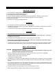
SAFETY IMPORTANT NOTICES 1. 2. 3. 4. 5. 6. 7. Read instructions carefully before installing and starting the UPS All warnings in the manual should be adhered to. All operating instructions should be followed. The unit should be supplied by a grounded outlet. Do not operate the unit without a ground source. Power cord of the UPS should be routed carefully so that they are not to be walked on. Please save this manual. Please save or recycle the packaging materials.
I. GENERAL DESCRIPTION 1.3 Introduction INFORM PDSP Series Uninterruptible Power Supplies are double-conversion, on-line UPS’s, manufactured with the latest IGBT and PWM technology, to produce an uninterruptible, microprocessor controlled pure sine wave output to critical loads.
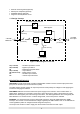
• • • • Remote monitoring Panel (Optional) RS232 port multiplexer (Optional) MODBUS adapter (Optional) Diagnostic and adjustment via PC. 1.2 Design Concept Maintenance Bypass Switch Static Bypass S3 SB S2 (F4-F5-F6) 3 PHASE MAINS I/P S1 (F1-F2-F3) K1 - ̃- ̃ Rectifier / Charger K2 Inverter S4 (F7-F8-F9) 3 PHASE AC Output S5 (F10-F11-F12) Battery (Dual Polarity) Figure 1.
STATIC TRANSFER SWITCH (STATIC BYPASS) : This is an electronically controlled transfer switch, which enables the critical load to be connected either to inverter output or to a by-pass power source. During normal operation, the load is supplied by the inverter output, but in case of an overload it is automatically transferred to the bypass source without any interruption.
Battery CB Input Emergency Stop Line Failure Relay Battery Low Relay Bypass Relay ( RS232 / SNMP ) Communication Select Switch Dry Relay Output Contacts Parallel Communication Sockets S6 Manual Bypass Switch S7 ON/OFF Switch S4 AC Output Switch S3 Maintenance Bypass Switch S2 Static Bypass Switch S1 AC Input Switch S5 Battery Input Switch Figure 1.
1.
II. UPS INSTALLATION 2.1 Introduction WARNING!!! • Do not apply electrical power to the UPS equipment before the arrival of authorized service personnel. • The UPS equipment should be installed only by qualified service personnel. • The connection of the batteries and the maintenance should be done by qualified service personnel. • Do not make any short- circuit to the battery poles. Because of high voltage and high short-circuit current, there is risk of electrical shock or burn.
Otherwise, the UPS and the load connected to the output will be left ungrounded. The grounding system must be checked, and must be strengthen if required. Potential difference between ground and neutral must be less than 3V AC. Descriptions of the UPS input output cable connection terminals are shown in figure 2.1 Recommended input line cable and fuse ratings are given in the table below.
2.4.5 UPS Power Cable Connection Terminals : 1 0 AC OUTPUTS 1 0 BYPASS INPUTS 1 0 AC LINKS TO BYPASS INPUT AC INPUTS 1 0 AC INPUT FUSES AC INPUT NEUTRAL BYPASS AND OUTPUT NEUTRAL 1 0 NEUTRAL BUSBAR BATTERY FUSES BATTERY BATTERY BATTERY INPUT Figure 2.
NOTES : • As shown on the power cable connection diagram of the UPS, U1, V1 and W1 phase of the incoming 3 phase supply are used as the bypass inputs under normal conditions, if there is not a separate bypass supply (split bypass). (U1, V1, W1 and U2, V2, W2 are the same in this case) • If there is a separate 3- phase AC supply for bypass (Split Bypass): a-) Remove the links from AC Inputs to Bypass Inputs.
NEUTRAL BUSBAR NÖTR BARASI BATTERY AKÜ K1 + (+) 360V +++++- 30x12V Batts. +++++- 30x12V Batts. K2 K2 (0) (0) BATTERY AKÜ K3 360V Figure 2.
UPS NEUTRAL BUSBAR BATT. BATT. 30x12V BATTS. 30x12V BATTS. Figure 2.
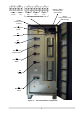
III. FRONT PANEL 3.1 Introduction The front panel of UPS, consisting of a 2 lines alphanumeric display, 6 status lamps, plus 4 function keys, allows the complete monitoring of the UPS status. The mimic flow diagram helps to comprehend the operating status of the UPS. By using the function keys operator can move on menus and change some parameters. Figure 3-1 Line Battery By-pass Maint.Sw. Inverter O/P Sw.
3.2.9 MEASURES Menu Items In this menu you can see all measured values. Use (↑) and (↓) keys for moving on submenu items. Submenu item LD%: 060 074 080 OPV: 220 221 220 FREQU: 50.0 Hz IPV: 240 235 220 BYP: 230 232 231 IPI: 022 010 030 +BATT: 405 V 000 A 7 -BATT: 405 V 000 A 8 TEMP: 030 c 9 BATT.
3.2.12 ADJUST Menu Items: Only service personnel can use this menu ,the incorrect use of this menu can cause damage to the UPS. Submenu item 1 PASSWORD : XXX 2 ENTER Go to STATUS MENU Function Service password input (-) key 100, UP key 10, (+) key 1 changes after you write the password on screen press ENTER key ,if the password is wrong the is no action. If the password is okay a beep sounds and you see ADJUST MODE at the second line. → Enter (↵ ) exit from submenu 3.2.
3.2.14 COMMAND Menu Items This menu is used to give various commands, to the UPS or to perform some tests on it. . Submenu items 1 SOUND : ON/OFF 2 ENTER B.TEST>405 3 ENTER Function Used for turning on/off the audible alarm. If you press ENTER key the option will change (push ON, push OFF) If the OFF option is selected, audible alarm is turned off but in case of a new alarm, UPS changes the option to ON state. If you press enter for 3 seconds battery test starts and lasts for 15 seconds.
3.2.15 TIME MENU ITEMS You can see date and time of RTC (real time clock) on UPS. And you can adjust date and time.
FAULT STATUS: In some cases controller checks events but can not find solutions, in this case controller decide to stop the system. For restarting the user must turn off the ON/OFF switch and turn it on again. WARNING STATUS: Some events recorded to log event file stays on LCD PANEL but UPS continues to work, these messages named as warning messages, user can clear this messages by pressing ENTER key for 3 seconds. These are: • A20 Boost charge alert • A6 Charge fault • A18 Batt capacity low 3.
ALARM A9 OVERLOAD Possible Causes: A10 LINE FAILURE Possible Causes: A11 HIGH TEMPER A12 OVERCURRENT A13 OUTPUT LOW A14 BATTERY HIGH A15 FUSE FAILURE DESCRIPTION UPS loaded more than 100% of nominal power rating. This state is may be continous or temporary. When this alarm is continous check the loads connected to the UPS output. Line failure. 1) Mains may be off. 2) Check all three input phases. 3) Check UPS input fuses. Overtemperature 1) Overload for inverter 2) Excessive ambient temperature.
ALARM P.FAILURE 21 P.TEST MODE P FAILURE 23 DUBL UPS NR. Possible Causes: PSP FAILURE1 DESCRIPTION Parallel controller board failure A28 Parallel controller is in test mode A29 Parallel controller board failure A30 Same UPS number is used for two UPS in the parallel system. A31 1) Change number(s) in OPTIONS Menu. Control Power supply fault. A39 One of parallel modes is selected but there is no parallel control board A40 CANT FIND PR on UPS Change mode from OPTIONS Menu.
IV. PARALLEL OPERATION 4.1 Introduction Two (or more) identical PDSP series UPSs can be interconnected for parallel operation. The main purposes for parallel use of PDSP series UPSs are: -Redundancy for Increased Reliability -Power Increase Although recent UPS designs are perfect and have high MTBF figures, a second (or more) UPS can be used in parallel with the first one, for supplying the critical load in case of any possible failure of the first UPS.
The AC inputs of all UPSs in the parallel system are connected to the same mains, and all the AC outputs are connected to each other. Each UPS has its own battery group. The critical load is connected to the common output of the parallel system. There are also some signal cable connections between the UPS units necessary for parallel operation, and will be described later. 4.
If this mode is active, you will see ‘’REDUNDT. MODE/MS’’ on the LCD panel of one of the UPS units, and you will see ‘’REDUNDT. MODE/SL’’ on the LCD panels of all the other UPS units connected in the parallel system. As explained above, higher degree of reliability for supplying a critical load can be obtained by choosing REDUNDANT mode for parallel operation and using as many as possible parallel connected UPSs. 4.2.3.
Parallel Parallel Port 1 Port 2 Parallel Parallel Port 1 Port 2 Parallel Parallel Port 1 Port 2 Figure 4.2.b 3 units in parallel Note: One purpose-built signal cable (DB25) is provided for each UPS unit in the parallel system. Parallel signal cables are interconnected between the UPS units to form a loop, as shown in figure 4.2, for having higher reliability against any possible signal cable failures. After completing the parallel connection of all the UPS units as shown in Figures 4.2 and 4.
MAIN AC INPUT U1 V1 W1 N1 K1 + K1 + K1 - K2 - K2 - K2 + K2 + K2 + K2 - K3 - K3 - K3 BATTERIES UPS1 BATTERIES AC OUTPUT1 UPS2 AC OUTPUT2 K12 K13 K14 U K12 K13 K14 U V W N FUSES BATTERIES V W N FUSES K11 K9 K10 K7 K8 K6 K4 + K5 K11 K9 K10 K7 K8 K6 K4 K5 K9 K10 K7 K8 K6 K4 K5 K11 BYPASS AC INPUT U2 V2 W2 N2 UPS3 AC OUTPUT3 K12 K13 K14 U V W N FUSES AC OUTPUT LOAD BRAKE SWITCH AC DISTRIBUTION BOARD U V W N LOAD Figure 4.
V. OPERATING INSTRUCTIONS 5.1 INTRODUCTION After completing the installation of the unit, and connecting all the power cables with all switches and fuses in “OFF” position, 1. Check the battery polarities. K1 : + V (+360V Nominal, +405V under float charge) K2 - K2 (NEUTRAL BUSBAR) : 0 Volts (connected to the midpoint of the 60 blocks battery string) K3 : - V (-360V Nominal, -405V under float charge) 2. Check the 3 phase AC input and neutral connections.
5.2.3 Switching into Maintenance Bypass Mode 1. Use “DOWN” button to choose COMMAND MENU and press ENTER. Use “DOWN” button again to reach ENTER message. Press ENTER, the UPS will switch into bypass mode. “MANUAL BYPASS” and “A52 MANUA. BYPASS” messages will appear on the screen. 2. Remove the padlock on S3 (Maintenance Bypass Switch) and turn it on into “1” position. 3. Turn off S7, S5, S1, S2 and S4.
7. Turn off S7 (ON-OFF) and after a few seconds turn it on again. UPS wilt start running again. 8. When “INVERTER START” message appears on the front panel turn on S5 (Battery) into “1”. Perform the same procedure given above for all UPS units. Make sure that all the units have the same operating mode but different UPS numbers. 9. Turn on S4 (AC Output) switches of all UPSs one by one. Now the parallel UPS system is ready to supply the critical load. 5.3.
VI. MAINTENANCE WARNING!!! DO NOT OPEN the covers of the UPS because there are no user serviceable parts inside. DO NOT TOUCH battery leads. There is high voltage even if the UPS is off. Therefore no one should open the covers of the UPS except authorized service personnel. Otherwise, serious injuries may occur. 6.1 Scheduled Maintenance Some semiconductor devices inside the UPS do not require any maintenance. Cooling fans are the only moving parts.
6.4 Annual maintenance To get reliable and efficient performance from the UPS, please call the qualified service personal at least once a year. 6.5 UPS Storage and transportation 1. Check the batteries charge by performing manual battery test before storage. If the charge is not enough then charge the batteries at least for 12 hours. 2. Qualified service personal should disconnect the electrical connections. 3. Batteries should be charged every six months during storage period. 4.
VII. FAULTS AND TROUBLESHOOTING 7.1 General Procedure For Fault Checking And Troubleshooting UPS contains complicated electronic control circuits. In order to locate any fault occurring circuits, an advanced knowledge about the circuitry and its operation principles must be known. The aim of this section is to give the knowledge required at the first intervention. There is no practical way to locate any possible fault. Most of the faults do not occur as a performance decrement.
VIII. UPS REMOTE MONITORING AND CONTROL Following external connections are available for PDSP series UPSs. • • • Communication by serial port connection. Dry contact (interface board) connections. Remote monitoring panel. 8.1 Using Serial Port A standard Serial (RS232) communication port is installed to all PDSP series UPS. By using this port user can get all information about the UPS. All measured parameters and alarms can be monitored via this port.
In “RS232” position of DIP switches, RS232 communication with an external device is performed through the standard DB9 socket shown above. If DIP switches are in “INTERNAL” position, communication through the standard socket is turned off and routed to an internally connected device.
8.3.3 Modem programming procedure Smart modem (SM) is the one connected to PC, and NULL Modem (NM) is the one connected to the UPS. Standard Hayes AT programming language is the suitable language for modems. In usual applications a modem which uses AT command set should be selected. 8.3.3.1 SMART Modem Programming (PC modem) The connected modem to PC (smart modem) will be programmed from UPS control software automatically.
Static Transfer Switch Battery Circuit Breaker Input Emergency Stop Line Failure Relay Battery Low Relay By-Pass Relay CN4 CN3 NOTE: Emergency stop terminals (4 and 5) should be short circuited by an external EPO switch to apply an EMERGENCY POWER OFF to the UPS (No output voltage). Line Failure, Battery Low and Bypass relays are normally de-energized and they are energized only in case of an alarm. The behavior of these relays can be reversed by the user. (i.e.